
Page 86 - Troubleshooting Analog Circuits
P. 86
Optoisolators 73
liamps of current, LEDs are awfully reliable these days. I have a thermometer display
on my wall, which has 650 inexpensive, plastic-packaged LEDS. These LEDs have
amassed 40,000,000 device-hours with just one failure. The only problem I ever have
with LEDs is trying to remember which lead is “plus”-I just measure the diode and
re-derive it, every time.
Optoisolators
An optoisolator, also called a photo-coupler or opto-coupler, usually consists of an
infrared LED and a sensitive phototransistor to detect the LED’s radiation. In the
course of working with the cheaper 4N28s, I’ve found it necessary to add circuitry to
achieve moderate speeds. For example, if you tailor the biasses per Figure 6.5, you
can get a 4N28’s response up toward 50 kHz; otherwise the devices can’t make even
4 kHz reliably. The trick is decreasing the phototransistor’s turn-off time by using a
resistor from pin 4 to pin 6.
I’ve evaluated many different makes and lots of 4N28s and have found widely
divergent responses. For example, the overall current gain at 8 mA can vary from 15
to 104%, even though the spec is simply 10% min. Further, the transfer efficiency
from the LED to the photodiode varies over a range wider than 10 1, and the p of the
transistor varies from 300 to 3000. Consequently, the transistor’s speed of response,
which is of course related to p and f3 dB, would vary over a 10 1 range.
If your circuit doesn’t allow for gains and frequency responses that vary so wildly
and widely, expect trouble. For example, two circuits, one an optoisolated switching
regulator (Ref. 3) and the other a detector for 4- to 20-mA currents (Ref. 4), have
enough degeneration so that any 4N28 you can buy will work. I used to have a group
of several “worst-case” 4N28s from various manufacturers that I would try out in
prototypes and problem circuits. Unfortunately, I don’t have those marginal devices
anymore, but they were pretty useful.
Also, the data sheets for optoelectronic components often don’t have a clear VF
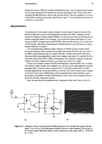
Figure 6.5. Adding RI and Rz to the inexpensive 4N28 optoisolator lets it handle faster signals with less
delay-5 ps vs. 60 ps. The scope photo’s bottom trace is an input waveform, the top trace is
the circuit’s output without RI and Rz, and the center trace is the output with RI = 2 MR and
Rz = I kfl.