
Page 34 - Tunable Lasers Handbook
P. 34
2 Narrow-tinewidth Laser Oscillators 15
3. PHYSICAL DIMENSIONS
An important initial condition necessary to achieve narrow-linewidth tunable
emission is to attain a single-transverse-mode laser beam profile. This is deter-
mined by the beam waist at the gain region and the cavity length. For example, a
laser-pumped dye laser, with the excitation laser focused to illuminate a gain vol-
ume 10 mm in length and 0.2 mm in diameter, would need a cavity length of -7
cm (at h -580 nm) to obtain a near TEM,, beam profile. Dimensions of the gain
region in laser-excited dye lasers are typically -10 mm in length with a cross-
sectional diameter in the 0.2- to 0.3-mm mge. These dimensions tend to yield
divergences near the diffraction limit in the 1- to 2-mrad range, at h -580 nm.
Flashlamp-pumped dye laser oscillators use gain regions of 10 to 40 cm in length
with cross-sectional diameters of -1 mm or less. For gas lasers, active lengths
can vary from 20 to more than 50 cm with cross-sectional diameters of -1 mm.
Semiconductor lasers, on the other hand, offer rather small dimensions with
active lengths in the submillimeter range and with cross-sectional dimensions in
the micrometer regime.
Diffraction gratings are commercially available in the following varieties:
1200, 2400, 3000, 3600, and 4300 l/mm. Usually the grating length is 5 cm but
gratings up to 15 cm long have been used [21-231.
The generalized theory and design of multiple-prism beam expanders have
been described in detail by Duarte [ 1,2,34-361. The basic elements of this theory
are presented in Section 7. In essence, an intracavity multiple-prism beam
expander for a HMPGI oscillator incorporating four prisms to yield a beam mag-
nification factor of M = 30 and a transmission factor of 0.76 can be designed to
Anti-Reflective
Coating
1-
J
Laser + \
output Partially
Reflective
Coating
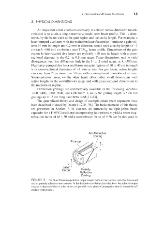
FIGURE 3 The Glm-Thompson polarizer output coupler with its inner surface antireflection coated
and its partially reflective outer surface. In the dispersive oscillators described here, the polarizer output
coupler is deployed with its polarization axis parallel to the plane of propagation (that is, rotated by d2
relative to this figure).