
Page 413 - Tunable Lasers Handbook
P. 413
8 Tunable External-Cavity Semiconductor lasers 37
Placing the laser diode in an external cavity with wavelength-selective feedback
narrows the spectral width by replacing the solitary diode spectrum with a small
number of closely spaced external-cavity modes (ideally a single mode).
The width of each individual mode is also narrowed by the external cavity.
The ratio of external-cavity to solitary diode linewidth is given by [39]
(1 + k)
-2
6ve,, =
where T~~~ and T~~~ are, respectively. the round-trip times of the solitary and exter-
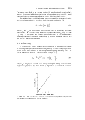
nal cavities. The external-cavity linewidth is proportional to P;:, (Fig. 12) and
L;;t (Fig. 113). The power and cavity length dependencies of the linewidth have
been experimentally confirmed, respectively. by workers at British Telecom [40]
and at AT&rT Bell Laboratories [41].
4.4 Multimoding
ECLs sometimes have a tendency to exhibit a state of multimode oscillation
in which rapid hopping between several neighboring external-cavity longitudinal
modes occurs. One estimate of the average mode-hopping frequency for a 1.3-
pm InGaAsP laser diode in a 7.5-cm external cavity is [42]
where T~ is the photon lifetime. Even though a complete theory is not available,
multimodhg behavior has been found to depend on a number of additional
.-
5 4
c
._
1 2 3 4 5
-1 il:. 2 0 0
Reciprocal output power, mW-'
FIGURE 1 2 ECL 1ineu.idth versus reciprocal power dependence. (Reproduced with permission
from Wyatt et al. [30] and Chapman and Hall Pub1ishers.j