
Page 420 - Tunable Lasers Handbook
P. 420
380 Paul Zorabedian
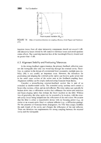
Peak-to-peak Variation (W&)
FIGURE 1 6 Effect of wavefront distortion on coupling efficiency (from Wagner and Tomlinson
[471).
insertion losses from all other intracavity components should not exceed 4 dB.
All intracavity lenses should be AR coated to minimize losses and avoid spurious
etalon effects. The round-trip insertion loss of the wavelength filter(s) should total
no greater than -3 dB.
6.3 Alignment Stability and Positioning Tolerances
In the strong-feedback approximation, the primary feedback reflection reen-
ters the waveguide after only one round-trip through the external cavity. There-
fore, in contrast to the design of conventional laser resonators, multiple-pass sta-
bility [48] is not usually an important issue. However, the tolerances for
positioning and aligning the external-cavity optics can become quite severe due
to the small cross section of the active area at the feedback-coupling facet.
Alignment stability can be simply analyzed using Gaussian beam theory.
Consider a retroreflecting external-feedback section that is part of an
extended or double-ended cavity. The extended cavity sections each contain a
beam relay section, a filter, and an end reflector. The relay optics can typically be
broken down into a collimation section that collimates the active-area emission
and beam-shaping optics that reshape the beam incident on the filter. Without
loss of generality, the relay optics can be assumed to be lossless, with the exter-
nal-cavity losses being lumped into the reflectance of the end mirror. We assume
that the filter is either a transmission device with no focusing power (e.g., an
etalon or an acousto-optic filter) or a planar reflector (e.g., a diffraction grating).
For the purposes of Gaussian beam propagation, the filter then simply modifies
the path length of the cavity and changes the reflectance of the end reflector.
There are therefore two requirements for strong coupling between the external
cavity and the waveguide: