Page 494 - Tunable Lasers Handbook
P. 494
454      Stephen Vincent Benson

                                                            -1,
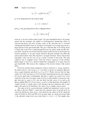
                                       qE = [l + 44K'ENp /A)']   -  .            (7)


                  qf is the filling factor for the optical mode


                  and q,u is the gain degradation due to slippage effects


                  where o- is the rms electron pulse length. The gain degradation due to the energy
                  spread  and the  emittance  are  similar  to  inhomogeneous  broadening  effects in
                  conventional  lasers  and  arise  because  some  of  the  electrons  have  a  resonant
                  wavelength that differs from the resonant wavelength of an average electron by a
                  large fraction of the gain bandwidth. The gain reduction due to the filling factor
                  is simply the result of an overlap integral between the optical mode and the elec-
                  tron beam. Equation (8) assumes that the optical mode and the electron beam are
                  focused  optimally  in the gain  region. Because  the gain medium  can affect the
                  actual optical mode waist, this equation is an approximation. Three-dimensional
                  simulation  codes  can  be  used  to  get  a  better  estimate  of  this  term.  The  gain
                  reduction  due to  slippage  occurs  tvhen  the  Fourier  transform  of  the  electron
                  bunch  shape in time has a spectral bandwidth comparable to or larger than the
                  gain  bandwidth. This reduces the coupling  of  the electron beam  to the optical
                  pulse.
                      Given the electron-beam parameters such as emittance E.  energy spread om
                                                                                   I'
                  the peak current I. and energy y,  it is possible  to design an undulator that pro-
                  duces a gain reduction parameter q,  or q  of 0.5. Warren showed that for large
                                                    -f.
                  values of &/A the harmonic at which both gain degradation factors were equal to
                  0.5 can be quite high. Unfortunately.  the gain is usually  too small to be useful
                  when this is the case. For small values of E/?L it is still possible to design the wig-
                  gler  that  sets  q,  equal  to  0.5, and  one  finds  that  the  values  of  q, and  qf are
                  always greater than 0.5. If one wants to work at a high harmonic, the number of
                  wiggler periods  is usually  quite small. Because the gain reduction due to slip-
                  page is the same for all harmonics, the value of q,  is usually close to unity.
                      The value of Q for a given harmonic number and optimum K varies very lit-
                  tle. This is shown in Table 1. which lists the optimum value for Q and the K for
                  which the maximum value occurs. Also listed are the values of K for which the
                  value of Q falls by 10% and 50% from its peak value. As can be seen from Table
                   1. the optimum value for Q vanes little from h = 3 to h = 15. This implies that.

