
Page 501 - Tunable Lasers Handbook
P. 501
9 Tunable Free-Electron Lasers 46%
range of wavelength coverage as possible. This section describes the major facil-
ities available now and one facility that is scheduled to come on line shortly.
More detailed information can be obtained from the individual institutions.
Interested readers can contact the institution which seems to have the best match
of capabilities and submit a proposal to use their facility. Each facility has
strengths and weaknesses and is best matched to a given range of experiments.
For each laboratory. I will describe the available wavelength range, the power
available over the wavelength range. the temporal and spectral structure, and any
unique features of the facility. Most of the facilities are driven by rf linacs and
therefore have a micropulse/macropulse structure. so the power quoted in the lit-
erature may be peak power during the micropulse, average power during the
macropulse, or, rarely, the long-term average power. One can also quote
micropulse energy or macropulse energy. For most research applications average
power is unimportant. The energy per macropulse and micropulse and the pulse
lengths are usually the most important quantities. For all the facilities, the mode
quality is nearly diffraction limited, so that feature will not be discussed here.
Another common feature is that the lasers are generally locked to the a-c line
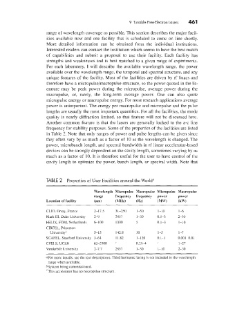
frequency for stability purposes. Some of the properties of the facilities are listed
in Table 2. Note that only ranges of power and pulse lengths can be giwn since
they often vary by as much as a factor of 10 as the wavelength is changed. The
power, microbunch length, and spectral bandwidth in rf linear accelerator-based
devices can be strongly dependent on the cavity length, sometimes varying by as
much as a factor of 10. It is therefore useful for the user to have control of the
cavity length to optimize the power, bunch length, or spectral width. Note that
TABLE 2 Properties of User Facilities around the World"
IValelength Micropulse Macropulse Micropulse Macropulse
range frequency frequency power power
Location of facility (pm) (MHz) tHz) (MW) (kW)
CLIO. Orsaj. France 2-17.5 31-250 1-50 1-10 1-6
Mark 111. Duke University 3-9 2857 1-30 0.5-3 2-30
FELIX. FOM, Netherlands 6-100 1000 3 0.1-3 1-10
CIRFEL, Princeton
Universityb 5-15 142.8 10 1-5 1-7
SCAFEL, Stanford University 3-61 11.82 1-120 0.1-1 0.001-0.01
CFELS. UCSB 62-2500 /' 0.25-4 1-27
Vanderbilt University 2-7.7 2857 1-30 1-10 2-30
aFor more details. see the texr descriptions. Third harmonic lasing is not included in the wavelength
range whez available.
bSystem being commissioned.
'This accelerator has no micropulse structure.