
Page 143 - Understanding Automotive Electronics
P. 143
2735 | CH 4 Page 130 Tuesday, March 10, 1998 11:06 AM
4 MICROCOMPUTER INSTRUMENTATION AND CONTROL
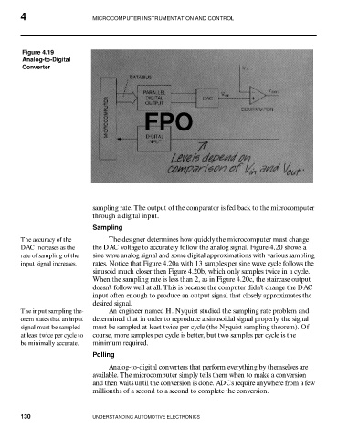
Figure 4.19
Analog-to-Digital
Converter
FPO
sampling rate. The output of the comparator is fed back to the microcomputer
through a digital input.
Sampling
The accuracy of the The designer determines how quickly the microcomputer must change
DAC increases as the the DAC voltage to accurately follow the analog signal. Figure 4.20 shows a
rate of sampling of the sine wave analog signal and some digital approximations with various sampling
input signal increases. rates. Notice that Figure 4.20a with 13 samples per sine wave cycle follows the
sinusoid much closer then Figure 4.20b, which only samples twice in a cycle.
When the sampling rate is less than 2, as in Figure 4.20c, the staircase output
doesn’t follow well at all. This is because the computer didn’t change the DAC
input often enough to produce an output signal that closely approximates the
desired signal.
The input sampling the- An engineer named H. Nyquist studied the sampling rate problem and
orem states that an input determined that in order to reproduce a sinusoidal signal properly, the signal
signal must be sampled must be sampled at least twice per cycle (the Nyquist sampling theorem). Of
at least twice per cycle to course, more samples per cycle is better, but two samples per cycle is the
be minimally accurate. minimum required.
Polling
Analog-to-digital converters that perform everything by themselves are
available. The microcomputer simply tells them when to make a conversion
and then waits until the conversion is done. ADCs require anywhere from a few
millionths of a second to a second to complete the conversion.
130 UNDERSTANDING AUTOMOTIVE ELECTRONICS