
Page 153 - Understanding Automotive Electronics
P. 153
2735 | CH 4 Page 140 Tuesday, March 10, 1998 11:06 AM
4 MICROCOMPUTER INSTRUMENTATION AND CONTROL
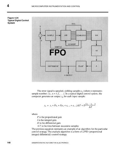
Figure 4.24
Typical Digital Control
System
FPO
The error signal is sampled, yielding samples e (where n represents
n
sample number; i.e., n = 1,2, . . .). In a typical digital control system, the
computer generates an output y for each input sample:
n
( e n – e n 1– )
(
y n = y o + Pe n + Ie n + e n 1– + e n 2– )∆T + D-----------------------
∆T
where
P is the proportional gain
I is the integral gain
D is the differential gain
∆ T is the time between successive samples
The previous equation represents an example of an algorithm for the particular
control strategy. The example algorithm is a form of a PID (proportional
integral differential) control strategy.
140 UNDERSTANDING AUTOMOTIVE ELECTRONICS