
Page 255 - Understanding Automotive Electronics
P. 255
2735 | CH 7 Page 242 Tuesday, March 10, 1998 1:15 PM
7 DIGITAL ENGINE CONTROL SYSTEM
Figure 7.9b
Distributorless
Ignition System
FPO
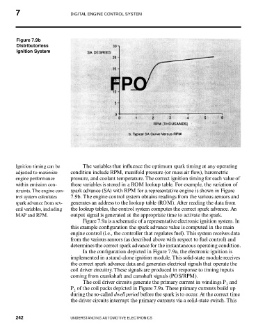
Ignition timing can be The variables that influence the optimum spark timing at any operating
adjusted to maximize condition include RPM, manifold pressure (or mass air flow), barometric
engine performance pressure, and coolant temperature. The correct ignition timing for each value of
within emission con- these variables is stored in a ROM lookup table. For example, the variation of
straints. The engine con- spark advance (SA) with RPM for a representative engine is shown in Figure
trol system calculates 7.9b. The engine control system obtains readings from the various sensors and
spark advance from sev- generates an address to the lookup table (ROM). After reading the data from
eral variables, including the lookup tables, the control system computes the correct spark advance. An
MAP and RPM. output signal is generated at the appropriate time to activate the spark.
Figure 7.9a is a schematic of a representative electronic ignition system. In
this example configuration the spark advance value is computed in the main
engine control (i.e., the controller that regulates fuel). This system receives data
from the various sensors (as described above with respect to fuel control) and
determines the correct spark advance for the instantaneous operating condition.
In the configuration depicted in Figure 7.9a, the electronic ignition is
implemented in a stand-alone ignition module. This solid-state module receives
the correct spark advance data and generates electrical signals that operate the
coil driver circuitry. These signals are produced in response to timing inputs
coming from crankshaft and camshaft signals (POS/RPM).
The coil driver circuits generate the primary current in windings P and
1
P of the coil packs depicted in Figure 7.9a. These primary currents build up
2
during the so-called dwell period before the spark is to occur. At the correct time
the driver circuits interrupt the primary currents via a solid-state switch. This
242 UNDERSTANDING AUTOMOTIVE ELECTRONICS