
Page 261 - Understanding Automotive Electronics
P. 261
2735 | CH 7 Page 248 Tuesday, March 10, 1998 1:15 PM
7 DIGITAL ENGINE CONTROL SYSTEM
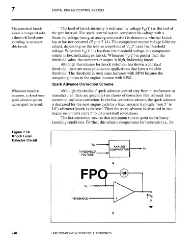
The acoustical knock The level of knock intensity is indicated by voltage V (T ) at the end of
K
signal is compared with the gate interval. The spark control system compares this voltage with a
a threshold level corre- threshold voltage (using an analog comparator) to determine whether knock
sponding to unaccept- has or has not occurred (Figure 7.14). The comparator output voltage is binary
able knock. valued, depending on the relative amplitude of V (T ) and the threshold
K
voltage. Whenever V (T ) is less than the threshold voltage, the comparator
K
output is low, indicating no knock. Whenever V (T ) is greater than the
K
threshold value, the comparator output is high, indicating knock.
Although this scheme for knock detection has shown a constant
threshold, there are some production applications that have a variable
threshold. The threshold in such cases increases with RPM because the
competing noises in the engine increase with RPM.
Spark Advance Correction Scheme
Whenever knock is Although the details of spark advance control vary from manufacturer to
excessive, a closed-loop manufacturer, there are generally two classes of correction that are used: fast
spark advance system correction and slow correction. In the fast correction scheme, the spark advance
causes spark to retard. is decreased for the next engine cycle by a fixed amount (typically from 5˚ to
10˚) whenever knock is detected. Then the spark advance is advanced in one-
degree increments every 5 to 20 crankshaft revolutions.
The fast correction ensures that minimum time is spent under heavy
knocking conditions. Further, this scheme compensates for hysteresis (i.e., for
Figure 7.14
Knock Level
Detector Circuit
FPO
248 UNDERSTANDING AUTOMOTIVE ELECTRONICS