
Page 270 - Understanding Automotive Electronics
P. 270
2735 | CH 7 Page 257 Tuesday, March 10, 1998 1:15 PM
DIGITAL ENGINE CONTROL SYSTEM 7
is packaged in such a way that this heat is largely maintained within the sensor
housing, thereby leading to a relatively rapid temperature rise.
Normally, the heating element need only be turned on for cold-start
operations. Shortly after engine start the exhaust gas has sufficient heat to
maintain the EGO sensor at a suitable temperature.
Fuel Injection Timing
Earlier in this chapter, the fuel control methods and algorithms were
explained for a sequential multipoint fuel injection system. In such a fuel
control system, it was shown that a separate fuel injector is provided for each
cylinder. The fuel injector for each cylinder is typically mounted in the intake
manifold such that fuel is sprayed directly into the intake port of the
corresponding cylinder during the intake stroke.
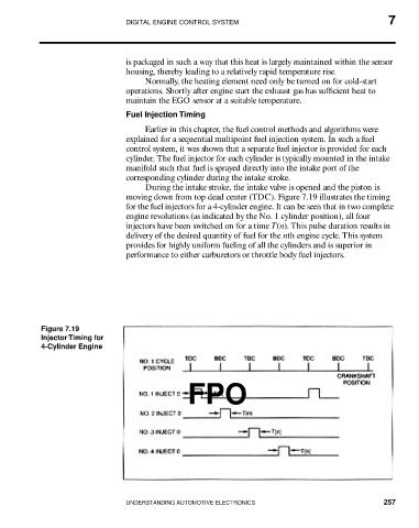
During the intake stroke, the intake valve is opened and the piston is
moving down from top dead center (TDC). Figure 7.19 illustrates the timing
for the fuel injectors for a 4-cylinder engine. It can be seen that in two complete
engine revolutions (as indicated by the No. 1 cylinder position), all four
injectors have been switched on for a time T(n). This pulse duration results in
delivery of the desired quantity of fuel for the nth engine cycle. This system
provides for highly uniform fueling of all the cylinders and is superior in
performance to either carburetors or throttle body fuel injectors.
Figure 7.19
Injector Timing for
4-Cylinder Engine
FPO
UNDERSTANDING AUTOMOTIVE ELECTRONICS 257