
Page 280 - Understanding Automotive Electronics
P. 280
2735 | CH 8 Page 267 Tuesday, March 10, 1998 1:19 PM
VEHICLE MOTION CONTROL 8
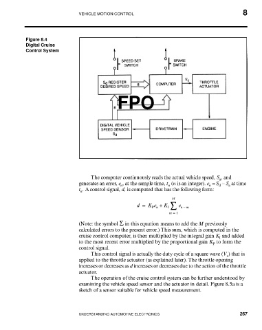
Figure 8.4
Digital Cruise
Control System
FPO
The computer continuously reads the actual vehicle speed, S , and
a
generates an error, e , at the sample time, t (n is an integer). e = S – S at time
a
n
d
n
n
t . A control signal, d, is computed that has the following form:
n
M
d = K e + K I ∑ e n – m
P n
m = 1
(Note: the symbol Σ in this equation means to add the M previously
calculated errors to the present error.) This sum, which is computed in the
cruise control computer, is then multiplied by the integral gain K and added
I
to the most recent error multiplied by the proportional gain K to form the
P
control signal.
This control signal is actually the duty cycle of a square wave (V ) that is
c
applied to the throttle actuator (as explained later). The throttle opening
increases or decreases as d increases or decreases due to the action of the throttle
actuator.
The operation of the cruise control system can be further understood by
examining the vehicle speed sensor and the actuator in detail. Figure 8.5a is a
sketch of a sensor suitable for vehicle speed measurement.
UNDERSTANDING AUTOMOTIVE ELECTRONICS 267