
Page 187 - Understanding Flight
P. 187
CH07_Anderson 7/25/01 9:00 AM Page 174
174 CHAPTER SEVEN
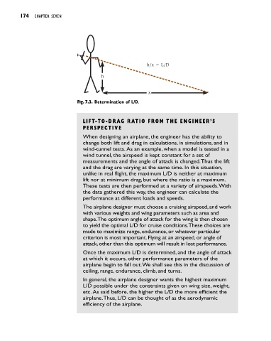
h/x = L/D
h
x
Fig. 7.3. Determination of L/D.
LIFT-TO-DRAG RATIO FROM THE ENGINEER’S
PERSPECTIVE
When designing an airplane, the engineer has the ability to
change both lift and drag in calculations, in simulations, and in
wind-tunnel tests. As an example, when a model is tested in a
wind tunnel, the airspeed is kept constant for a set of
measurements and the angle of attack is changed.Thus the lift
and the drag are varying at the same time. In this situation,
unlike in real flight, the maximum L/D is neither at maximum
lift nor at minimum drag, but where the ratio is a maximum.
These tests are then performed at a variety of airspeeds.With
the data gathered this way, the engineer can calculate the
performance at different loads and speeds.
The airplane designer must choose a cruising airspeed, and work
with various weights and wing parameters such as area and
shape.The optimum angle of attack for the wing is then chosen
to yield the optimal L/D for cruise conditions.These choices are
made to maximize range, endurance, or whatever particular
criterion is most important. Flying at an airspeed, or angle of
attack, other than this optimum will result in lost performance.
Once the maximum L/D is determined, and the angle of attack
at which it occurs, other performance parameters of the
airplane begin to fall out.We shall see this in the discussion of
ceiling, range, endurance, climb, and turns.
In general, the airplane designer wants the highest maximum
L/D possible under the constraints given on wing size, weight,
etc. As said before, the higher the L/D the more efficient the
airplane.Thus, L/D can be thought of as the aerodynamic
efficiency of the airplane.