
Page 207 - Urban Construction Project Management
P. 207
162 Chapter Six
and possibly soften and shift the soil in the surrounding area on which the foundations
of the building may bear. In order to stop groundwater from entering the site, draw
down sumps can be created around the site to depress the entire water table in the sur-
rounding area. This process utilizes vertical pipes with screened openings at the bottom
to keep soil in place and allow water to enter. The water has to be discharged away from
the site to prevent it from potentially re-entering. Discharge from such wells is often
regulated by various jurisdictions. The PM may be required to obtain permits for the
project to allow for the legal discharge of the water. Piezometers, which measure the
water elevation in the surrounding area, are also utilized to monitor the draw down
curve of the surrounding area and its water table. Sometimes, when excavating to a
lower elevation at the site, a series of rings of well points may be required to properly
draw down the water table of the site and the adjacent areas. The lowering of the water
table by well points in the surrounding area can have an adverse effect on neighboring
buildings. It can cause consolidation or settlement of the surrounding soil under the
adjacent building foundations. It can also expose untreated wood pilings that were pre-
viously immersed in subsurface water to air and possible decay. It is recommended that
a geotechnical engineering consultant be retained to determine the subsurface condi-
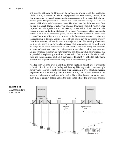
tions and the appropriate method of dewatering. Exhibit 6-41 indicates water being
pumped utilizing well points monitoring wells in the surrounding area.
Another approach is to erect a watertight barrier creating a bathtub effect around the
entire site. See the section on shoring and sheeting. This only works if the watertight
barrier walls go down to the bottom edge of an impermeable layer of subsoil material
to prevent water from seeping under the walls. A slurry wall is often utilized in this
situation, and makes a good watertight barrier. Sheet piling is sometimes used; how-
ever, it has a tendency to leak around the joints in the piling. The hydrostatic pressure
Exhibit 6-41
Dewatering draw Building Building
down curve.
Monitoring
wells Pump Pump
Original Original water
grade table
Draw down curve of
lowered water level
after pumping