
Page 162 - Using ANSYS for Finite Element Analysis Dynamic, Probabilistic, Design and Heat Transfer Analysis
P. 162
apDl programming • 149
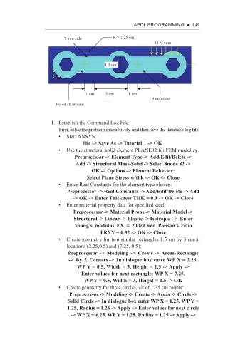
7 mm side R = 1.25 cm
88 N / cm
1.5 cm
1 cm 3 cm 1 cm
9 mm side
Fixed all around
1. Establish the Command Log File
First, solve the problem interactively and then save the database log file.
• Start ANSYS
File -> Save As -> Tutorial 1 -> OK
• Use the structural solid element PLANE82 for FEM modeling:
Preprocessor -> Element Type -> Add/Edit/Delete ->
Add -> Structural Mass-Solid -> Select 8node 82 ->
OK -> Options -> Element Behavior:
Select Plane Stress w/thk -> OK -> Close
• Enter Real Constants for the element type chosen:
Preprocessor -> Real Constants -> Add/Edit/Delete -> Add
-> OK -> Enter Thickness THK = 0.3 -> OK -> Close
• Enter material property data for specified steel:
Preprocessor -> Material Props -> Material Model ->
Structural -> Linear -> Elastic -> Isotropic -> Enter
Young’s modulus EX = 200e9 and Poisson’s ratio
PRXY = 0.32 -> OK -> Close
• Create geometry for two similar rectangles 1.5 cm by 3 cm at
locations (2.25,0.5) and (7.25, 0.5):
Preprocessor -> Modeling -> Create -> Areas-Rectangle
-> By 2 Corners -> In dialogue box enter WP X = 2.25,
WP Y = 0.5, Width = 3, Height = 1.5 -> Apply ->
Enter values for next rectangle: WP X = 7.25,
WP Y = 0.5, Width = 3, Height = 1.5 -> OK
• Create geometry for three circles, all of 1.25 cm radius:
Preprocessor -> Modeling -> Create -> Areas -> Circle ->
Solid Circle -> In dialogue box enter WP X = 1.25, WP Y =
1.25, Radius = 1.25 -> Apply -> Enter values for next circle
-> WP X = 6.25, WP Y = 1.25, Radius = 1.25 -> Apply ->