
Page 194 - Using ANSYS for Finite Element Analysis Dynamic, Probabilistic, Design and Heat Transfer Analysis
P. 194
Design optimization • 181
No matter how you intend to create the analysis file, the basic
information that it must contain is the same. The steps it must
include are explained next.
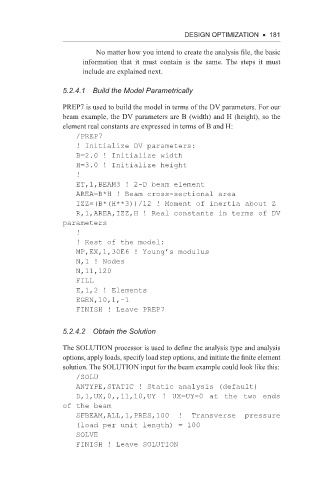
5.2.4.1 build the Model Parametrically
PREP7 is used to build the model in terms of the DV parameters. For our
beam example, the DV parameters are B (width) and H (height), so the
element real constants are expressed in terms of B and H:
/PREP7
! Initialize DV parameters:
B=2.0 ! Initialize width
H=3.0 ! Initialize height
!
ET,1,BEAM3 ! 2-D beam element
AREA=B*H ! Beam cross-sectional area
IZZ=(B*(H**3))/12 ! Moment of inertia about Z
R,1,AREA,IZZ,H ! Real constants in terms of DV
parameters
!
! Rest of the model:
MP,EX,1,30E6 ! Young’s modulus
N,1 ! Nodes
N,11,120
FILL
E,1,2 ! Elements
EGEN,10,1,-1
FINISH ! Leave PREP7
5.2.4.2 obtain the Solution
The SOLUTION processor is used to define the analysis type and analysis
options, apply loads, specify load step options, and initiate the finite element
solution. The SOLUTION input for the beam example could look like this:
/SOLU
ANTYPE,STATIC ! Static analysis (default)
D,1,UX,0,,11,10,UY ! UX=UY=0 at the two ends
of the beam
SFBEAM,ALL,1,PRES,100 ! Transverse pressure
(load per unit length) = 100
SOLVE
FINISH ! Leave SOLUTION