
Page 116 - Using ANSYS for Finite Element Analysis A Tutorial for Engineers
P. 116
stAtIc AnAlysIs usIng lIne elements • 103
This location is fixed, which means that all translational and rota-
tional degrees of freedom (DOFs) are constrained. Therefore, select All
DOF by clicking on it and enter 0 in the Value field and click OK.
You will see some blue triangles in the Graphics window indicating
the displacement constraints. Using the same method, apply the roller con-
nection to the right end (UY constrained). Note that more than one DOF
constraint can be selected at a time in the Apply U, ROT on KPs window.
Therefore, you may need to deselect the All DOF option to select just the
UY option.
13. Apply loads.
As shown in the diagram, there are four downward loads of 280kN,
210kN, 280kN, and 360kN at keypoints 1, 3, 5, and 7, respectively. Select:
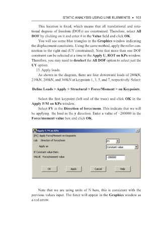
Define Loads > Apply > Structural > Force/Moment > on Keypoints.
Select the first keypoint (left end of the truss) and click OK in the
Apply F/M on KPs window.
Select FY in the Direction of force/mom. This indicate that we will
be applying the load in the y direction. Enter a value of −280000 in the
Force/moment value box and click OK.
Note that we are using units of N here, this is consistent with the
previous values input. The force will appear in the Graphics window as
a red arrow.