
Page 161 - Using ANSYS for Finite Element Analysis A Tutorial for Engineers
P. 161
148 • Using ansys for finite element analysis
Solution Methodology
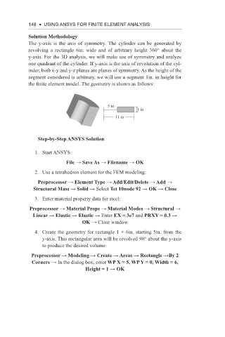
The y-axis is the axis of symmetry. The cylinder can be generated by
revolving a rectangle 6in. wide and of arbitrary height 360° about the
y-axis. For the 3D analysis, we will make use of symmetry and analyze
one quadrant of the cylinder. If y-axis is the axis of revolution of the cyl-
inder, both x-y and y-z planes are planes of symmetry. As the height of the
segment considered is arbitrary, we will use a segment 1in. in height for
the finite element model. The geometry is shown as follows:
5 in
1 in
11 in
Step-by-Step ANSYS Solution
1. Start ANSYS:
File → Save As → Filename → OK
2. Use a tetrahedron element for the FEM modeling:
Preprocessor → Element Type → Add/Edit/Delete → Add →
Structural Mass → Solid → Select Tet 10node 92 → OK → Close
3. Enter material property data for steel:
Preprocessor → Material Props → Material Modes → Structural →
Linear → Elastic → Elastic → Enter EX = 3e7 and PRXY = 0.3 →
OK → Close window
4. Create the geometry for rectangle 1 × 6in. starting 5in. from the
y-axis. This rectangular area will be revolved 90° about the y-axis
to produce the desired volume:
Preprocessor → Modeling → Create → Areas → Rectangle →By 2
Corners → In the dialog box, enter WP X = 5, WP Y = 0, Width = 6,
Height = 1 → OK