
Page 558 - Materials Chemistry, Second Edition
P. 558
CAT3525_C17.qxd 1/27/2005 12:44 PM Page 529
Land Disposal of Hazardous Waste 529
geomembrane cap is placed over the low permeability clay cap and below the SWCR system
(Figure 17.7). Geomembrane caps function primarily by preventing surface water including pre-
cipitation from entering the landfill. In selecting materials for the geomembrane cap, operators
should keep in mind some practical differences between liners and caps. Unlike a liner, a geomem-
brane cap is usually not exposed to leachate, so chemical compatibility is not a significant issue.
Membrane caps also have lower stresses acting on them in comparison with liners. An advantage
geomembrane caps have over liners is that they are much easier to repair due to their proximity to
the surface of the landfill. Geomembrane caps will, however, be subject to other strains due to
settlement of the waste (U.S. EPA, 1989).
17.3.10 SURFACE WATER COLLECTION AND REMOVAL SYSTEM
The surface water collection and removal (SWCR) system is installed on top of the completed unit
and directly above the geomembrane cap (Figure 17.7). The purpose of the SWCR system is to
prevent the infiltration of surface water into the landfill by diverting and removing any liquid that
comes into contact with it. Surface water is redirected to the perimeter of the cover system. The
rainwater that percolates through the topsoil and vegetative cover is carried off to an upper
drainage system.
Surface water drainage systems can be composed of granular soils, geonets, or geocomposites,
but the majority of drainage systems use granular soil. This is significant in frost-susceptible
regions, where a 1 to 2 m (3 to 6 ft) soil layer is needed above the geomembrane liner to protect
against frost penetration. In such cases, a 0.3 m (1 ft) layer of granular soil serves as the surface
water collector. If good drainage materials are not available or if the site is too large, a synthetic
geonet or geocomposite can be used. The advantage of drainage geocomposites is their higher flow
rate capabilities compared with geonets or granular soils. All geocomposite systems are designed
with polymer cores protected by a geotextile filter. Many of the polymers cannot withstand highly
reactive leachates; however, in a surface drainage collector, the only contact is with water and
leachate will not be encountered.
Figure 17.8 shows a typical landfill profile designed to meet the EPA minimum technology
guidance requirements. The upper profile includes the soil cover, a 1 ft lateral drainage layer, and a
low permeability cap of barrier soil (clay), which must be more than 2 ft thick. This three-layer sys-
tem also includes a geomembrane cap and an optional gas control layer.
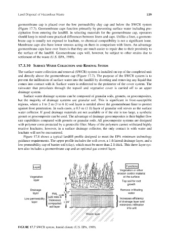
Layer Functions
Vegetation or other
erosion control material
Vegetative at the surface
layer Top soil for root
≥ 24" growth
Drainage Remove infiltrating
layer FML ≥ 12" water
(≥20 mils in
Low permeability thickness) Increases efficiency
layer ≥ 24" of drainage layer and
compacted minimizes infiltration
soil layer
into unit
Waste layer
FIGURE 17.7 SWCR system, humid climate (U.S. EPA, 1989).