
Page 102 - Wastewater Solids Incineration Systems
P. 102
Combustion Technology 71
obtained before they reach the bed surface where carry-over may occur. It is impor-
tant that the feed cake release its maximum energy to the sand bed to counteract the
quenching effect of water evaporation.
Depending on the diameter of the furnace, there are usually two or four feed
injection points to ensure that the cake is evenly distributed throughout the bed.
7.3 Sand System
Sand-like material is used as bed media. The furnace is typically filled with sand to a
static height of 0.9 m (3 ft). When the fluid bed is in operation, the bed material will
expand, because of fluidizing air, to a height of about 1.5 m (5 ft). With time, the sand
gets abraded, and makeup is required. Makeup sand can be pneumatically fed into
the furnace during normal operation. The feed system is generally of the dense-phase
type pneumatic conveying.
Bed removal systems have been provided with some existing systems to cool the
sand. It’s critically important to remember that removing sand from a hot bed is
unsafe. As a safety precaution, sand should be removed from the bed when the fur-
nace has been cooled and the sand bed is at about 38°C (100°F).
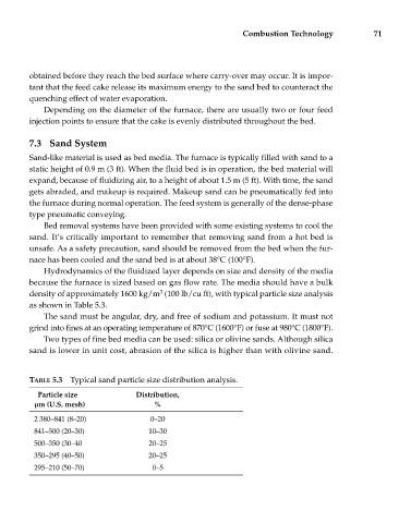
Hydrodynamics of the fluidized layer depends on size and density of the media
because the furnace is sized based on gas flow rate. The media should have a bulk
3
density of approximately 1600 kg/m (100 lb/cu ft), with typical particle size analysis
as shown in Table 5.3.
The sand must be angular, dry, and free of sodium and potassium. It must not
grind into fines at an operating temperature of 870°C (1600°F) or fuse at 980°C (1800°F).
Two types of fine bed media can be used: silica or olivine sands. Although silica
sand is lower in unit cost, abrasion of the silica is higher than with olivine sand.
TABLE 5.3 Typical sand particle size distribution analysis.
Particle size Distribution,
μm (U.S. mesh) %
2 380–841 (8–20) 0–20
841–500 (20–30) 10–30
500–350 (30–40 20–25
350–295 (40–50) 20–25
295–210 (50–70) 0–5