
Page 137 - Water Engineering Hydraulics, Distribution and Treatment
P. 137
B
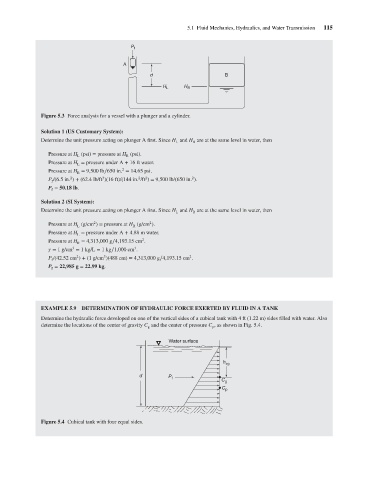
Figure 5.3 Force analysis for a vessel with a plunger and a cylinder.
Solution 1 (US Customary System): A P f d H L H R 5.1 Fluid Mechanics, Hydraulics, and Water Transmission 115
Determine the unit pressure acting on plunger A first. Since H and H are at the same level in water, then
L
R
Pressure at H (psi) = pressure at H (psi).
L
R
Pressure at H = pressure under A + 16 ft water.
L
2
Pressure at H = 9,500 lb∕650 in. = 14.65 psi.
R
2
2
3
2
2
P /(6.5 in. ) + (62.4 lb/ft )(16 ft)/(144 in. /ft ) = 9,500 lb/(650 in. ).
f
P = 50.18 lb.
f
Solution 2 (SI System):
Determine the unit pressure acting on plunger A first. Since H and H are at the same level in water, then
L R
2
2
Pressure at H (g/cm ) = pressure at H (g/cm ).
R
L
Pressure at H = pressure under A + 4.88 m water.
L
2
Pressure at H = 4,313,000 g∕4,193.15 cm .
R
3
3
= 1 g/cm = 1 kg/L = 1kg∕1,000 cm .
3
2
2
P /(42.52 cm ) + (1 g/cm )(488 cm) = 4,313,000 g∕4,193.15 cm .
f
P = 22,985 g = 22.99 kg.
f
EXAMPLE 5.9 DETERMINATION OF HYDRAULIC FORCE EXERTED BY FLUID IN A TANK
Determine the hydraulic force developed on one of the vertical sides of a cubical tank with 4 ft (1.22 m) sides filled with water. Also
determine the locations of the center of gravity C and the center of pressure C , as shown in Fig. 5.4.
g p
Water surface
h cg
d P
f
C g
C p
Figure 5.4 Cubical tank with four equal sides.