Page 151 - Water Engineering Hydraulics, Distribution and Treatment
P. 151

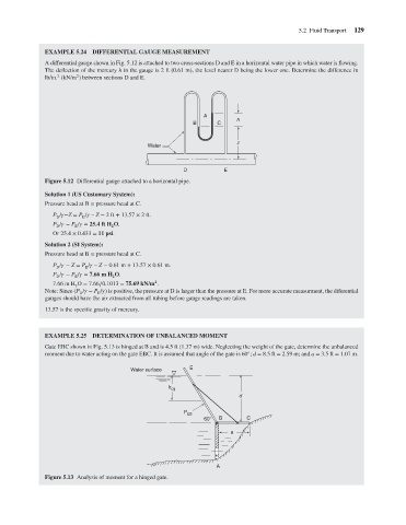
EXAMPLE 5.24 DIFFERENTIAL GAUGE MEASUREMENT
                                      A differential gauge shown in Fig. 5.12 is attached to two cross-sections D and E in a horizontal water pipe in which water is flowing.
                                      The deflection of the mercury h in the gauge is 2 ft (0.61 m), the level nearer D being the lower one. Determine the difference in
                                               2
                                         2
                                      lb/in. (kN/m ) between sections D and E.
                                                                                      A
                                                                                          C
                                                                                  B
                                                                                                z h               5.2 Fluid Transport  129
                                                                     Water
                                                                               D            E
                                      Figure 5.12 Differential gauge attached to a horizontal pipe.
                                      Solution 1 (US Customary System):
                                      Pressure head at B = pressure head at C.
                                        P /  −Z = P /   – Z − 2ft + 13.57 × 2ft.
                                                 E
                                         D
                                        P /   − P /   = 25.4 ft H O.
                                         D
                                               E
                                                          2
                                        Or 25.4 × 0.433 = 11 psi.
                                      Solution 2 (SI System):
                                      Pressure head at B = pressure head at C.
                                        P /   − Z = P /   – Z − 0.61 m + 13.57 × 0.61 m.
                                         D        E
                                        P /   − P /   = 7.66 m H O.
                                         D     E          2
                                                                       2
                                        7.66 m H O = 7.66∕0.1013 = 75.69 kN/m .
                                               2
                                      Note: Since (P /   − P /  ) is positive, the pressure at D is larger than the pressure at E. For more accurate measurment, the diferential
                                                      E
                                                D
                                      gauges should have the air extracted from all tubing before gauge readings are taken.
                                      13.57 is the specific gravity of mercury.
                                      EXAMPLE 5.25 DETERMINATION OF UNBALANCED MOMENT
                                      Gate EBC shown in Fig. 5.13 is hinged at B and is 4.5 ft (1.37 m) wide. Neglecting the weight of the gate, determine the unbalanced
                                                                                                   ◦
                                      moment due to water acting on the gate EBC. It is assumed that angle of the gate is 60 ; d = 8.5 ft = 2.59 m; and a = 3.5 ft = 1.07 m.
                                                                Water surface    E


                                                                           h cg
                                                                                                d


                                                                                P EB
                                                                                      60°  B       C
                                                                                              a


                                                                                         A
                                      Figure 5.13 Analysis of moment for a hinged gate.
   146   147   148   149   150   151   152   153   154   155   156