
Page 257 - Water and Wastewater Engineering Design Principles and Practice
P. 257
6-34 WATER AND WASTEWATER ENGINEERING
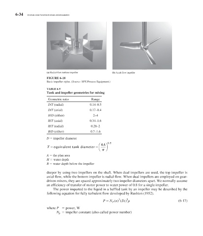
(a) Radial-flow turbine impeller (b) Axial-flow impeller
FIGURE 6-18
Basic impeller styles. (Source: SPX Process Equipment.)
TABLE 6-5
Tank and impeller geometries for mixing
Geometric ratio Range
D/T (radial) 0.14–0.5
D/T (axial) 0.17–0.4
H/D (either) 2–4
H/T (axial) 0.34–1.6
H/T (radial) 0.28–2
B/D (either) 0.7–1.6
D impeller diameter
.
⎛ 4 A ⎞ 0 5
T equivalent tank diameter
⎝ ⎠
A the plan area
H water depth
B water depth below the impeller
deeper by using two impellers on the shaft. When dual impellers are used, the top impeller is
axial flow, while the bottom impeller is radial flow. When dual impellers are employed on gear-
driven mixers, they are spaced approximately two impeller diameters apart. We normally assume
an efficiency of transfer of motor power to water power of 0.8 for a single impeller.
The power imparted to the liquid in a baffled tank by an impeller may be described by the
following equation for fully turbulent flow developed by Rushton (1952).
3
P N n () ( 5 (6-17)
p
Di)
where P power, W
N p impeller constant (also called power number)