
Page 153 - Whole Earth Geophysics An Introductory Textbook For Geologists And Geophysicists
P. 153
135 coef- Hz 80 Hz 40 criti- 7, through the fold in would
Exercises 1000 re 50 50 1000 reflection of 20 10 trace. of 10 10 trace. Rayleigh; iii) of zero m, 500 m, of 500 m. 1 is plotted events events
h= h= = h h= wavelet seismic wavelet fl direct reflection. distance instead locations time. What the Which
2.2; ont =2.4; 2.1; 2.2; impedance, and zero-phase resulting zero-phase resulting seismic m/s» ii) multiple a depth the of each of 5-2(a).
p = p = p p = 5-7 scale. a the a the ft m/s P; direct P arrivals at each at right the each in as
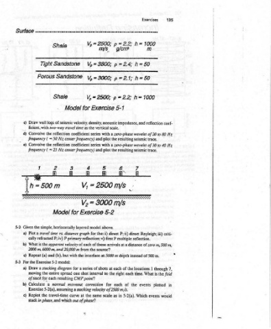
Vp = 2500; ms p 3800; V,= 3000; = vy, = 2500; V, Exercise for velocity, density. acoustic vertical the as with series and plot with series plot and fi i 2500 = V, L7 3000 = V2 5-2 Exercise above. model layered i) the: for reflection; v) first of these source? the from at 5000 m interface the series of shots to interval shot CMP point? for corr
Shale Sandstone Sandstone Shale Model of seismic nvo-way travel time coefficient reflection Hz ~ 50 center frequency) coefficient reflection center frequency) Hz = 25 it it for Model simple, horizontally distance graph vs. primary P P; iv) velocity of each the apparent and 20,000 m with (b), but model: 5-2 a for diagram entire one spread resulting moveout normal 5-2(a), assu
Tight Porous logs well ficient, with the Convolve ( frequency the Convolve ( frequency 500m the travel time a cally refracted is 2000 m, 6000 m, and (a) Exercise stacking a the of stack for each a Calculate the in phase, and
Surface Draw c) _ d) e) i Given 5-2 Plot a) What b) Repeat c) For the §-3 Draw a) moving b) Exercise Replot c) stack
Analysis the Middle America Trench no interpretation; the uppermost 4.$ km of the turbidites side of right have turbidites water strong imped- acoustic sediments very to of regions sec- of the side more a have seismic of logs the as depth
Waveform turbidites on trench a to Hemipelagic homogeneous, leading Two zone). on the right regions wave velocities (V,), densities (p) well Draw with
And from section the water layer (zero amplitude); trench (“chaotic”). From G. F. Moore and T. H. Shipley. Mechanisms D. C. section, leading contrasting those strata. model}. coefficient,
Processing, CA mene top figure shows the seismic traces with interpretations superimposed. Note that the Union, Washington, the of the water, of layérs reflections. more “transparent” turbidites crust; oceanic sedimentary layer. the of reflection and
Acquisition, UATE migrated a on packages include of sediment accretion in the Middle America Trench off Mexico, in Journal of Geophysical Research, v.93, pp.8911-8927, Geophysical side left the than velocity have turbidites high-amplitude much are crust seismically trench deformed the of on the following page shows compressional of horizontal each for bottom the to
Reflection: eee io reflection amplitude); hemipelagic sediments (Jow amplitude, “transparent” zone); deformed On results. seismic and trench of sequence oceanic (a the basement layers for the acoustic impedance drilled is acoustic
Seismic SESS y? sigan Seismic waveform packages observed Mex-2; Moore and Shipley, 1988). The the bottom, but with (“chaotic” seismic expression): and oceanic crust traces density reflection. The a to the of top reflections layering include the crystalline random or “chaotic” seismic appearance. (h) thicknesses Calculate well a density, scale.
5 is shown on is not shown. Prominent © 1988. Redrawn with permission of the American seismic higher leading on amplitude and The model and a) Pretend b) velocity, vertical
Chapter at i i a Ser te ae blank much bottom ance, deposited low complex tion, 5-1
5.36 off Mexico (Line same section water column EXERCISES
134 FIGURE section
5.0 6.0 5.0 6.0 (high