
Page 198 - Fluid Power Engineering
P. 198
170 Chapter Nine
a rotor hub that is connected to the main shaft. In large utility-scale
turbines, the rotor hub has mechanisms to pitch the blade, that is,
rotate along the longitudinal axis of the blade.
Blades
Although turbine blades are, in principle, similar to airplane wings in
terms of generating lift, there are significant design differences.
Twist along the longitudinal axis of the blade. As discussed
in Chapter 4, in order to achieve a constant angle of attack
along the entire length of the blade, a twist is added to the
blade.
Turbine blades are thinner and longer because it yields en-
hanced performance in lower wind speed.
Stall characteristics are different. Wind turbines continue to
operate under stall conditions between rated and cut-out
wind speed, whereas an airplane avoids stall conditions.
Soiling of wind turbine blades with dust, dead insects, and
others can cause significant loss of power. Coupled with the
high expense of cleaning blades, this leads to a design chal-
lenge.
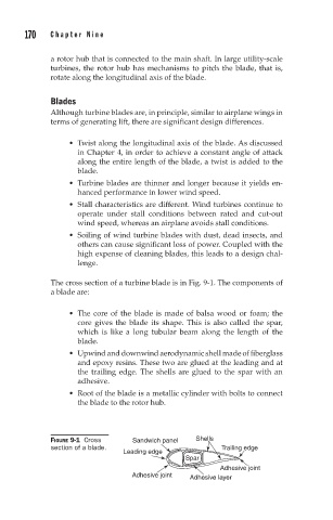
The cross section of a turbine blade is in Fig. 9-1. The components of
a blade are:
The core of the blade is made of balsa wood or foam; the
core gives the blade its shape. This is also called the spar,
which is like a long tubular beam along the length of the
blade.
Upwind and downwind aerodynamic shell made of fiberglass
and epoxy resins. These two are glued at the leading and at
the trailing edge. The shells are glued to the spar with an
adhesive.
Root of the blade is a metallic cylinder with bolts to connect
the blade to the rotor hub.
FIGURE 9-1 Cross Sandwich panel Shells
section of a blade. Trailing edge
Leading edge
Spar
Adhesive joint
Adhesive joint Adhesive layer