
Page 229 - Mechanical Behavior of Materials
P. 229
230 Chapter 5 Stress–Strain Relationships and Behavior
(a) Determine the stresses in the x- and y-directions, the strain in the z-direction, and the
volumetric strain.
(b) Evaluate the ratio of stress to strain for the z-direction, E = σ 2 /ε z , and comment on
the value obtained.
5.27 A block of material is confined by a rigid die as shown in Fig. P5.24, so that it cannot deform
in either the x-or y-directions. A compressive stress is applied in the z-direction. Assume
that there is no friction along the walls and that no yielding occurs in the metal. What is
the largest value of the compressive stress σ z that can be applied without the strain in the
z-direction exceeding 0.2% = 0.002?
5.28 For the solution of Fig. P5.25, the material is brass (70% Cu, 30% Zn), and the compressive
stresses applied in x- and y-directions are 80 and 120 MPa, respectively. What stress develops
in the z-direction, and what are the strains in the x- and y-directions?
5.29 For the situation of Fig. P5.25, where a rigid die prevents deformation in the z-direction, the
material is an aluminum alloy, and equal compressive stresses of 150 MPa are applied in the
x- and y-directions.
(a) Determine the stress in the z-direction, the strains in the x- and y-directions, and the
volumetric strain.
(b) Evaluate the ratio of stress to strain for the x-direction and comment on the value
obtained.
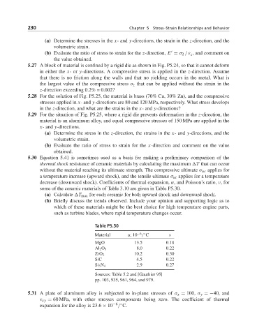
5.30 Equation 5.41 is sometimes used as a basis for making a preliminary comparison of the
thermal shock resistance of ceramic materials by calculating the maximum T that can occur
without the material reaching its ultimate strength. The compressive ultimate σ uc applies for
a temperature increase (upward shock), and the tensile ultimate σ ut applies for a temperature
decrease (downward shock). Coefficients of thermal expansion, α, and Poisson’s ratio, ν,for
some of the ceramic materials of Table 3.10 are given in Table P5.30.
(a) Calculate T max for each ceramic for both upward shock and downward shock.
(b) Briefly discuss the trends observed. Include your opinion and supporting logic as to
which of these materials might be the best choice for high temperature engine parts,
such as turbine blades, where rapid temperature changes occur.
Table P5.30
Material α, 10 / C ν
−6 ◦
MgO 13.5 0.18
Al 2 O 3 8.0 0.22
ZrO 2 10.2 0.30
SiC 4.5 0.22
Si 3 N 4 2.9 0.27
Sources: Table 5.2 and [Gauthier 95]
pp. 103, 935, 961, 964, and 979.
5.31 A plate of aluminum alloy is subjected to in-plane stresses of σ x = 100, σ y =−40, and
τ xy = 60 MPa, with other stresses components being zero. The coefficient of thermal
expansion for the alloy is 23.6 × 10 −6 ◦
/ C.