
Page 264 - Mechanical Behavior of Materials
P. 264
266 Chapter 6 Review of Complex and Principal States of Stress and Strain
such that the long diagonal (dashed line) of the resulting parallelogram is aligned with the larger
of ε 1 and ε 2 .
The remaining two principal shear strains can be obtained from Eq. 6.41:
γ 1 = |ε 2 − ε 3 | = 0.00058, γ 2 = |ε 1 − ε 3 | = 0.00558 Ans.
The same result for the in-plane strains can be obtained by using Mohr’s circle on a plot of
ε versus γ/2 as shown. Two ends of a diameter are given by
γ xy γ xy
ε x , − = (−0.0005, −0.0015), ε y , = (0.0035, 0.0015)
2 2
Analysis on the circle proceeds in a manner similar to that for stress. (See Fig. E6.8(d).) The
special dual sign convention needed for shear strain corresponds to that for the shear stress
which would produce the distortion, clockwise rotation being positive, as in Fig. 6.6.
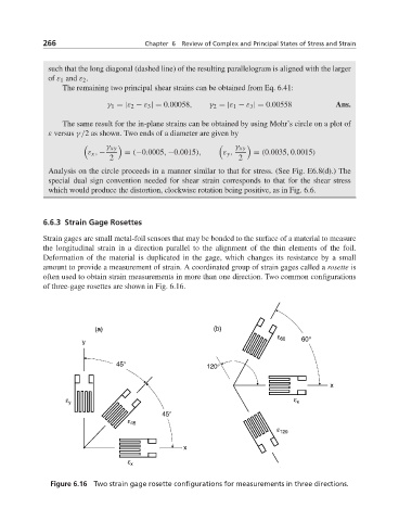
6.6.3 Strain Gage Rosettes
Strain gages are small metal-foil sensors that may be bonded to the surface of a material to measure
the longitudinal strain in a direction parallel to the alignment of the thin elements of the foil.
Deformation of the material is duplicated in the gage, which changes its resistance by a small
amount to provide a measurement of strain. A coordinated group of strain gages called a rosette is
often used to obtain strain measurements in more than one direction. Two common configurations
of three-gage rosettes are shown in Fig. 6.16.
Figure 6.16 Two strain gage rosette configurations for measurements in three directions.