
Page 143 - Introduction to Marine Engineering
P. 143
Pumps and pumping systems S29
Cover
Strainer plate
Body
Figure 6.16 Mud box
Suction pipes in tanks should be arranged with a bell mouth or foot.
The bell end or foot should provide an inlet area of about
one-and-a-half times the pipe area. It should also be a sufficient distance
from the bottom plating and nearby structure to provide a free suction
area, again about one-and-a-half times the pipe area.
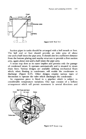
A steam trap does as its name implies and permits only the passage
of condensed steam. It operates automatically and is situated in steam
drain lines. Various designs are available utilising mechanical floats
which, when floating in condensate, will enable the condensate to
discharge (Figure 6.17). Other designs employ various types of
thermostat to operate the valve which discharges the condensate.
An expansion piece is fitted in a pipeline which is subject to
considerable temperature variations. One type consists of a bellows
arrangement which will permit movement in several directions and
Ball float and lever
Cover Air vent Body
Valve seat
Figure 6.17 Steam trap