
Page 437 - Moving the Earth_ The Workbook of Excavation
P. 437
BLASTING AND TUNNELING
BLASTING AND TUNNELING 9.37
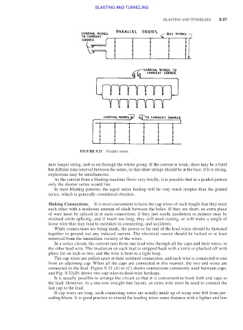
FIGURE 9.31 Parallel series.
next longer string, and so on through the whole group. If the current is weak, there may be a brief
but definite time interval between the series, so that short strings should be at the face. If it is strong,
explosions may be simultaneous.
As the current from a blasting machine flows very briefly, it is possible that in a graded pattern
only the shorter series would fire.
In most blasting patterns, the equal series hookup will be very much simpler than the graded
series, which is generally considered obsolete.
Making Connections. It is most convenient to have the cap wires of such length that they meet
each other with a moderate amount of slack between the holes. If they are short, an extra piece
of wire must be spliced in at each connection; if they just reach, insulation or primers may be
strained while splicing; and if much too long, they will need cutting, or will make a tangle of
loose wire that may lead to mistakes in connecting, and accidents.
While connections are being made, the power or far end of the lead wires should be fastened
together to ground out any induced current. The electrical source should be locked or at least
removed from the immediate vicinity of the wires.
In a series circuit, the current runs from one lead wire through all the caps and their wires, to
the other lead wire. The insulation on each lead is stripped back with a knife or plucked off with
pliers for an inch or two, and the wire is bent to a tight loop.
The cap wires are pulled apart at their soldered connection, and each wire is connected to one
from an adjoining cap. When all the caps are connected in this manner, the two end wires are
connected to the lead. Figure 9.32 (A) to (C) shows connections commonly used between caps,
and Fig. 9.32(D) shows two cap-wire-to-lead-wire hookups.
It is usually possible to arrange the circuit so that it is convenient to hook both end caps to
the lead. However, in a one-row straight-line layout, an extra wire must be used to connect the
last cap to the lead.
If cap wires are long, such connecting wires are usually made up of scrap wire left from pre-
ceding blasts. It is good practice to extend the leading wires some distance with a lighter and less