
Page 439 - Moving the Earth_ The Workbook of Excavation
P. 439
BLASTING AND TUNNELING
BLASTING AND TUNNELING 9.39
FIGURE 9.33 Protecting caps against stray currents.
other leg or the shunt, to one leg of the next cap which has its other leg connected to the return
lead. Making cuts where indicated will include the caps in a firing circuit which is closed until the
leads are separated at the battery end.
Even with these precautions, however, blasting should be discontinued if there is a thunder-
storm within 5 miles, or other severe hazards exist.
Crackling in a portable battery-type radio (not FM), left at high volume, provides warning of
approach of a thunderstorm.
Testing. A circuit tester should be used for checking before attempting to blast. This device consists
of a galvanometer and a silver chloride dry cell, which produces a current too weak to fire a standard
blasting cap. The lead or cap wires are fastened to its terminals, and the action of the indicator
needle shows the condition of the circuit.
If the circuit is good, the indicator needle will move an amount inversely proportional to the
resistance offered by the caps and wire used. If the needle does not move, there is an open break.
If it moves only slightly, a loose connection, or a break with wires just touching, is indicated. If
the needle moves farther than it should, a short or a ground is present.
Each hole may be tested before hooking into the circuit, and a single test may be made from
the power end of the lead wires when wiring is complete.
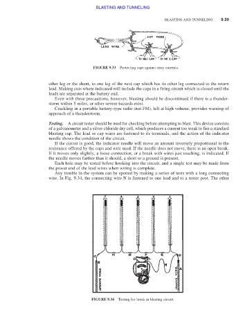
Any trouble in the system can be spotted by making a series of tests with a long connecting
wire. In Fig. 9.34, the connecting wire N is fastened to one lead and to a tester post. The other
FIGURE 9.34 Testing for break in blasting circuit.