
Page 107 -
P. 107
AERATION AND AIR STRIPPING 5.23
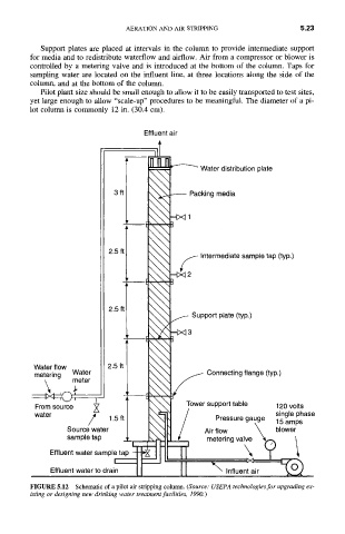
Support plates are placed at intervals in the column to provide intermediate support
for media and to redistribute waterflow and airflow. Air from a compressor or blower is
controlled by a metering valve and is introduced at the bottom of the column. Taps for
sampling water are located on the influent line, at three locations along the side of the
column, and at the bottom of the column.
Pilot plant size should be small enough to allow it to be easily transported to test sites,
yet large enough to allow "scale-up" procedures to be meaningful. The diameter of a pi-
lot column is commonly 12 in. (30.4 cm).
Effluent air
.ll
ii-
~ Water distribution plate
3 ft
cking media
Intermediate sample tap (typ.)
2.5 ft I
2.5
ft I Support plate (typ.)
3
Water flow 2.5 ft /
metering Water l Connecting flange (typ.)
\ meter I L
,
single phase
water / 1.5 ft ~4 Pressure gauge 15 amps
Source water ' Air flow blower
sampletap.' m~r,il ii~,~? ~
Effluent water sampler tap II "
Effluent water to drain [ [ I
FIGURE 5.12 Schematic of a pilot air stripping column. (Source: USEPA technologies for upgrading ex-
isting or designing new drinking water treatment facilities, 1990.)