
Page 136 -
P. 136
7.2 CHAPTER SEVEN
Rectilinear
flow/ Skirt
Influent CE ] // ~ | Effluent ~ ~
• I ~E3 ' Tank wall~/SS~ Effluent
Effluent \\1 ~ ~
launder , ~ ,"-...._ .j
(A) Rectangular settling tank, rectilinear flow Launder
~ j Launder ~, Influent
~
~/on~'-j "~u~)~l'~'~'~~Effluent (C) Peripheral--feed settling tank, spiralflow
Distributi / ~',~ /aunder-
well ~
Distribution
Effluent
~, Influent well /.~,(,~k,
(B) Center-feed settling tank, source flow
~ Effl,uent :.
U
Influent
(D) Peripheral-feed settling tank, radial flow (E) Square settling tank, radial flow
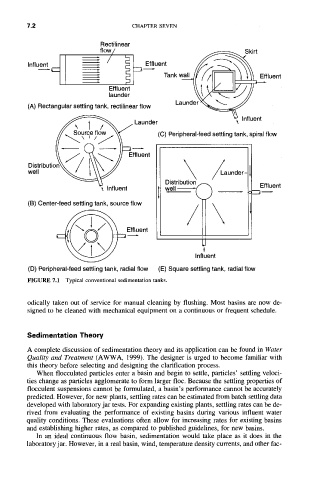
FIGURE 7.1 Typical conventional sedimentation tanks.
odically taken out of service for manual cleaning by flushing. Most basins are now de-
signed to be cleaned with mechanical equipment on a continuous or frequent schedule.
Sedimentation Theory
A complete discussion of sedimentation theory and its application can be found in Water
Quality and Treatment (AWWA, 1999). The designer is urged to become familiar with
this theory before selecting and designing the clarification process.
When flocculated particles enter a basin and begin to settle, particles' settling veloci-
ties change as particles agglomerate to form larger floc. Because the settling properties of
flocculent suspensions cannot be formulated, a basin's performance cannot be accurately
predicted. However, for new plants, settling rates can be estimated from batch settling data
developed with laboratory jar tests. For expanding existing plants, settling rates can be de-
rived from evaluating the performance of existing basins during various influent water
quality conditions. These evaluations often allow for increasing rates for existing basins
and establishing higher rates, as compared to published guidelines, for new basins.
In an ideal continuous flow basin, sedimentation would take place as it does in the
laboratory jar. However, in a real basin, wind, temperature density currents, and other fac-