
Page 131 -
P. 131
6.22 CHAPTER SIX
poses. Slots should be staggered to prevent short-circuiting. Normally the floors of hy-
draulic flocculation basins slope toward the discharge end to facilitate cleaning and to
provide tapered energy.
Generally, flocculation basins are designed to be approximately the same depth as the
adjacent clarifier.
End Baffles. Most flocculator systems require an end baffle between the flocculation
zone and the clarifier, or some provision to prevent residual energy from the flocculation
process from being transferred to the clarification stage. These baffles also minimize short-
circuiting and reduce the effects of water temperature changes.
End baffles may be designed on the same basis as compartmentalization baffles de-
scribed above. End baffles should not provide a barrier to removing sludge when the floc
basin is cleaned, and limited openings in the bottom of the baffle are appropriate. Simi-
larly, a small submerged section at the top of the baffle will allow scum to pass down-
stream.
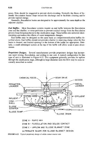
Proprietary Designs. Several manufacturers provide proprietary designs that incorpo-
rate rapid mixing, flocculation, and settling in one unit. A typical configuration for this
type of unit is illustrated in Figure 6.12. This equipment generally provides for upflow
through the clarification stage, although in large-diameter units the flow may be more ac-
curately described as radial.
PERIMETER\ I\ ~/~ I ,-/I /RADIAL
LAUNDER \ I 'yF~rl I / .KLAUNDER
• ~''" " ....... jAO-+ 31AI'TERNATI~/E~
tl " " /q I r-'N~HAPE ~'I,') I tl
/ 1-.1 STEEL HOOD---~/I==~ ==~\ C ,ql~[ [ I~--EFFLUENT
.N~LOENTI r.I ~, J,B ')' ,~ ",'// lil ll
CONC-- "i % OX~ ,,
//°?4
•
~~..-~-~--
SLUDGE ~ ~ '~ =
SCRAPER - - ~'~:~ ~ - ~ . ~ , .
SLUDGE SUMP -"I ~X'XSLUDGE DRAIN
ZONE A- RAPID MIX
ZONE B - FLOCCULATION AND SOLIDS CONTACT
ZONE C - UPFLOW AND SLUDGE BLANKET ZONE
ALTERNATE SHAPE FOR SLUDGE BLANKET DESIGN
FIGURE 6.12 Typical proprietary design of solids contact reactor unit.