
Page 130 -
P. 130
MIXING, COAGULATION, AND FLOCCULATION 6.21
INLET CONDUIT -
~--L ~ _
: )
~ ~ ..
)
BAFFLE
PLAN OF MAZE FLOCCULATOR
. . . .
-1- L L .... L-
t t L
L ..... L L .... I-
PLAN OF BAFFLE FLOCCULATOR
I I
= I
-SILL
/ I ! I I I
CLEANING~" ~
SLOTS - TYP.
SECTION
SECTION
M AZE FLOCCULATOR BAFFLE FLOCCULATOR
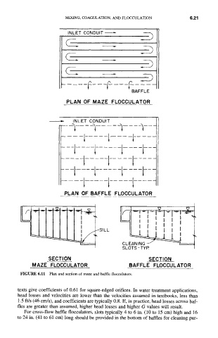
FIGURE 6.11
Plan and section of maze and baffle flocculators.
texts give coefficients of 0.61 for square-edged orifices. In water treatment applications,
head losses and velocities are lower than the velocities assumed in textbooks, less than
1.5 ft/s (46 ClrdS), and coefficients are typically 0.8. If, in practice, head losses across baf-
fles are greater than assumed, higher head losses and higher G values will result.
For cross-flow baffle flocculators, slots typically 4 to 6 in. (10 to 15 cm) high and 16
to 24 in. (41 to 61 cm) long should be provided in the bottom of baffles for cleaning put-