
Page 168 -
P. 168
CLARIFICATION 7.31
.. Sec ary • • g Oratt YuOes
" ~ ' , ' .2t / Rotor.,ml~e,,er ~d , U
L_~- :- -'~-=~:~
Blow-off anO drain
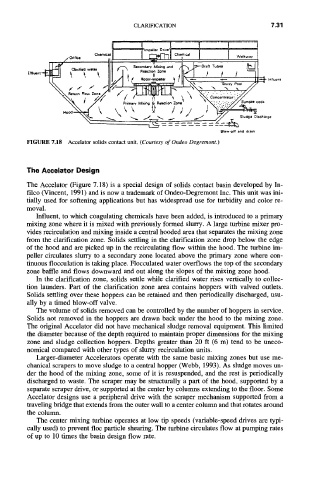
FIGURE 7.18 Accelator solids contact unit. (Courtesy of Ondeo Degremont.)
The Accelator Design
The Accelator (Figure 7.18) is a special design of solids contact basin developed by In-
filco (Vincent, 1991) and is now a trademark of Ondeo-Degremont Inc. This unit was ini-
tially used for softening applications but has widespread use for turbidity and color re-
moval.
Influent, to which coagulating chemicals have been added, is introduced to a primary
mixing zone where it is mixed with previously formed slurry. A large turbine mixer pro-
vides recirculation and mixing inside a central hooded area that separates the mixing zone
from the clarification zone. Solids settling in the clarification zone drop below the edge
of the hood and are picked up in the recirculating flow within the hood. The turbine im-
peller circulates slurry to a secondary zone located above the primary zone where con-
tinuous flocculation is taking place. Flocculated water overflows the top of the secondary
zone baffle and flows downward and out along the slopes of the mixing zone hood.
In the clarification zone, solids settle while clarified water rises vertically to collec-
tion launders. Part of the clarification zone area contains hoppers with valved outlets.
Solids settling over these hoppers can be retained and then periodically discharged, usu-
ally by a timed blow-off valve.
The volume of solids removed can be controlled by the number of hoppers in service.
Solids not removed in the hoppers are drawn back under the hood to the mixing zone.
The original Accelator did not have mechanical sludge removal equipment. This limited
the diameter because of the depth required to maintain proper dimensions for the mixing
zone and sludge collection hoppers. Depths greater than 20 ft (6 m) tend to be uneco-
nomical compared with other types of slurry recirculation units.
Larger-diameter Accelerators operate with the same basic mixing zones but use me-
chanical scrapers to move sludge to a central hopper (Webb, 1993). As sludge moves un-
der the hood of the mixing zone, some of it is resuspended, and the rest is periodically
discharged to waste. The scraper may be structurally a part of the hood, supported by a
separate scraper drive, or supported at the center by columns extending to the floor. Some
Accelator designs use a peripheral drive with the scraper mechanism supported from a
traveling bridge that extends from the outer wall to a center column and that rotates around
the column.
The center mixing turbine operates at low tip speeds (variable-speed drives are typi-
cally used) to prevent floc particle shearing. The turbine circulates flow at pumping rates
of up to 10 times the basin design flow rate.