
Page 163 -
P. 163
"/.26 CHAPTER SEVEN
low settled solids to slide down the inclined surface and drop into the basin below. Dis-
tance between plates is designed to provide an upflow velocity lower than the settling ve-
locity of the particles, allowing particles to settle to the plate surface. The effective set-
tling area is the horizontal projected area of the plate, calculated by multiplying the plate
area by the cosine of the angle of the plate to the horizontal. Total settling area is the sum
of the effective areas of each plate.
Design Criteria. The primary design criterion for plate settlers is the surface loading
rate for each plate. Typical loading rates range from 0.3 to 0.7 gpm/ft 2 (0.7 to 1.7 m/h),
depending on the settling characteristics of the solids, water temperature, and desired ef-
fluent quality. These loading rates allow for overall basin loadings from 2 to 6 gpm/ft 2 (5
to 15 m/h), several times those for conventional basins. This criterion allows for much
smaller basins in new construction or for up-rating existing basins.
Basin Dimensions. Plate settlers are typically manufactured in modules. Dimensions of
modules and plates vary by manufacturer and are proprietary. These proprietary dimen-
sions require different basin geometries, and the system designer must work with manu-
facturers to establish appropriate dimensions for new construction or to decide how plates
may be installed in existing basins. Some manufacturers provide standard-width plates of
varying heights to fit custom designs.
The basic dimensions provided by each manufacturer are primarily established by how
each manufacturer approaches the problem of flow control. Basin dimensions may also be
controlled by how the sludge is to be removed. Sludge removal devices are typically the
same as those used for conventional basins except those that travel on or above the sur-
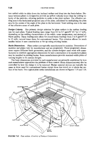
face of the basin. Two typical plate settler installations are shown in Figures 7.15 and 7.16.
FIGURE 7.15 Plate settlers. (Courtesy of Parkson Corporation.)