
Page 161 -
P. 161
CHAPTER SEVEN
7,24
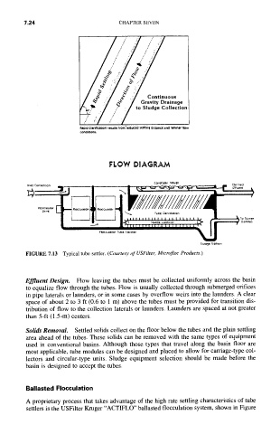
ReDI¢I clar;flcatJon results from'reOuced settlin~ clilltlncl and laminar flow
conditions.
FLOW DIAGRAM
Col~tcuon r*ou~n
Pn~t Connection . . . . . Clnrlfi¢o
~,. • I 'k--4.-~ --- ,-~--"~-~'.~-'- ~ I = ~ .......
II"
"-If Ill .... ............
., . . . . ' .... ~.:oI,'o',~'o ' ..... '.~ t~x~°~,,"
FIoccul4IOr TuOe CI4rl/icr
S~uaSe Si~on
FIGURE 7.13 Typical tube settler. (Courtesy of USFilter, Microfloc Products.)
Effluent Design. Flow leaving the tubes must be collected uniformly across the basin
to equalize flow through the tubes. Flow is usually collected through submerged orifices
in pipe laterals or launders, or in some cases by overflow weirs into the launders. A clear
space of about 2 to 3 ft (0.6 to 1 m) above the tubes must be provided for transition dis-
tribution of flow to the collection laterals or launders. Launders are spaced at not greater
than 5-ft (1.5-m) centers.
Solids Removal. Settled solids collect on the floor below the tubes and the plain settling
area ahead of the tubes. These solids can be removed with the same types of equipment
used in conventional basins. Although those types that travel along the basin floor are
most applicable, tube modules can be designed and placed to allow for carriage-type col-
lectors and circular-type units. Sludge equipment selection should be made before the
basin is designed to accept the tubes.
Ballasted Flocculation
A proprietary process that takes advantage of the high rate settling characteristics of tube
settlers is the USFilter Kruger "ACTIFLO" ballasted flocculation system, shown in Figure