
Page 157 -
P. 157
7.20 CHAPTER SEVEN
PLAN VIEW
........ , ................. ~ . / /o.o°2~;LoT/~7"
FL~CU~TION WEL "~LEAR~CE ~
cNor B~ E~MCO)
ILLUSTRATIVE SECTION
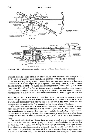
FIGURE 7.12 Typical flocculator clarifier. (Courtesy of Eimco Water Technologies.)
available standard sludge removal systems. Circular tanks have been built as large as 300
ft (91 m) in diameter but more typically are less than 100 ft (30 m) in diameter.
Although settling theory is based on overflow rate, side water depth is an important
consideration. Adequate depth mitigates hydraulic instability caused by wind currents,
thermal currents, hydraulic scour, and random sludge blanket disturbances. Typical depths
range from 10 to 15 ft (3 to 3.6 m). Because sludge is usually scraped to center hoppers,
basin bottoms are sloped to the center. Large-diameter basins have two slopes, one steeper
near the center to allow adequate depth to move the solids to central hoppers for removal.
Inlet Design. Flocculated water is usually introduced to the center of circular or square
basins through a center riser into a circular feed well. Some clarifier designs allow the in-
troduction of flocculated water into the side of the feed well. The intent of the feed well
is to produce a smooth, radial flow outward toward the periphery of the basin.
The center feed amounts to a point source, because the feed well seldom represents
more than 3% or 4% of basin area. For this reason, a great deal of flow mass is crowded
into a small space and does not flow in an exactly radial pattern, leading to hydraulic im-
balance and short-circuiting. This problem is accentuated in large-diameter shallow basins
at high surface overflow rates in the 800 to 1,500 gpd/ft 2 [33,000 to 61,000 (L/day)/m 2]
range.
One questionable feed well design involves using a small-diameter circular skirt of
about 1% of the basin area extending only 3 to 4 ft (0.9 to 1.2 m) below the surface. The
feed into this well is either from four ports discharging horizontally from a pier riser or
from a horizontal pipeline discharging horizontally into the well from just below the sur-
face. In the four-port design, variation of flow rate is accommodated with a design exit
flow of about 2 ft/s (61 cm/s). This, however, does not ensure equal egress from each port.