
Page 154 -
P. 154
CLARIFICATION 7.17
tor traveling the full length of the basin less frequently. This method of operation avoids
collecting a large volume of very low-solids water.
Instrument-quality compressed air at 100 psi (689 kPa) is supplied from a compressor
system to a local electric/pneumatic interface panel mounted at the basin. Air is provided
to the drive assembly and pneumatic sludge valves by means of umbilical hoses from the
control panel to the drive assembly and valves. At one end of the basin is an extractor as-
sembly consisting of vertical guide rails and a removable winch assembly to lift the col-
lector header out of the tank for maintenance.
Because these collectors do not require expensive sludge hoppers, they are a low-cost
option for retrofitting manually cleaned basins and since they do not require access from
the surface, they can also operate effectively beneath plate or tube settler systems.
Options to the pneumatically driven collectors include continuous stainless steel tapes
or chains, powered by a motor mounted at the top of one end of the basin, that pull the
collector pipe back and forth along the bottom-mounted rail.
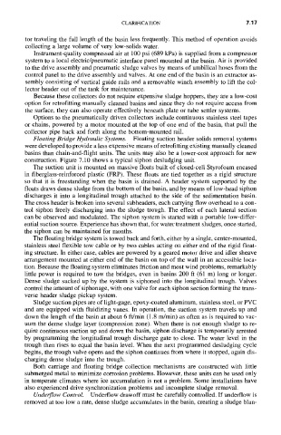
Floating Bridge Hydraulic Systems. Floating suction header solids removal systems
were developed to provide a less expensive means of retrofitting existing manually cleaned
basins than chain-and-flight units. The units may also be a lower-cost approach for new
construction. Figure 7.10 shows a typical siphon desludging unit.
The suction unit is mounted on massive floats built of closed-cell Styrofoam encased
in fiberglass-reinforced plastic (FRP). These floats are tied together as a rigid structure
so that it is freestanding when the basin is drained. A header system supported by the
floats draws dense sludge from the bottom of the basin, and by means of low-head siphon
discharges it into a longitudinal trough attached to the side of the sedimentation basin.
The cross header is broken into several subheaders, each carrying flow overhead to a con-
trol siphon freely discharging into the sludge trough. The effect of each lateral section
can be observed and modulated. The siphon system is started with a portable low-differ-
ential suction source. Experience has shown that, for water treatment sludges, once started,
the siphon can be maintained for months.
The floating bridge system is towed back and forth, either by a single, center-mounted,
stainless steel flexible tow cable or by two cables acting on either end of the rigid float-
ing structure. In either case, cables are powered by a geared motor drive and idler sheave
arrangement mounted at either end of the basin on top of the wall in an accessible loca-
tion. Because the floating system eliminates friction and most wind problems, remarkably
little power is required to tow the bridges, even in basins 200 ft (61 m) long or longer.
Dense sludge sucked up by the system is siphoned into the longitudinal trough. Valves
control the amount of siphonage, with one valve for each siphon section forming the trans-
verse header sludge pickup system.
Sludge suction pipes are of light-gage, epoxy-coated aluminum, stainless steel, or PVC
and are equipped with fluidizing vanes. In operation, the suction system travels up and
down the length of the basin at about 6 ft/min (1.8 rn/min) as often as is required to vac-
uum the dense sludge layer (compression zone). When there is not enough sludge to re-
quire continuous suction up and down the basin, siphon discharge is temporarily arrested
by programming the longitudinal trough discharge gate to close. The water level in the
trough then rises to equal the basin level. When the next programmed desludging cycle
begins, the trough valve opens and the siphon continues from where it stopped, again dis-
charging dense sludge into the trough.
Both carriage and floating bridge collection mechanisms are constructed with little
submerged metal to minimize corrosion problems. However, these units can be used only
in temperate climates where ice accumulation is not a problem. Some installations have
also experienced drive synchronization problems and incomplete sludge removal.
Underflow Control. Underflow drawoff must be carefully controlled. If underflow is
removed at too low a rate, dense sludge accumulates in the basin, creating a sludge blan-