
Page 149 -
P. 149
7.14 CHAPTER SEVEN
I-luHr~l dip r'lri~t¢~ i init
iles
)ars
and wear strip assembly.
Guide pipe
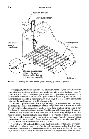
FIGURE 7.8 Indexing grid sludge removal system. (Courtesy of Parkson Corporation.)
Track-Mounted Hydraulic Systems. As shown in Figure 7.9, one type of hydraulic
removal system consists of a stainless steel header pipe with orifices sized and spaced for
proper sludge removal. The collector pipe is attached to a pneumatically controlled drive
assembly that travels on a stainless steel guide rail running the length of the tank. Col-
lector pipes are generally a maximum width of 20 to 25 ft (6.1 to 7.6 m), and multiple
units must be used to cover the width of wider tanks.
The collector pipe is attached to a sludge discharge pipe in the tank wall. The sludge
discharge pipe contains a pneumatically actuated sludge valve located below water level.
When the sludge valve is open, the water level in the basin creates a driving force to start
flow into and through the collector system. The drive assembly is pneumatically powered
to travel the length of the tank in both directions. As it moves along, sludge on the basin
floor is picked up hydraulically at a travel speed of 1.5 ft/min (0.46 m/min). The number
of times the collector traverses the tank must be determined from the volume of sludge
produced and the flow capacity of the collector system. This is typically about 90 gpm
(5.7 L/s), based on a differential head of 5 ft (1.5 m).
The system is fully automated through an electronic control system using a program-
mable logic controller to control how often the collector operates and the length of travel.
For example, because most of the sludge typically accumulates in the first third of a rec-
tangular basin, it is necessary to collect in that area on a frequent basis, with the collec-