
Page 144 -
P. 144
CLARIFICATION 7.9
:
5~. 4, .
.!'.,,~H :' ' ~0f Chain a re_..2, R_.*,, Ill, . '[U
oo. ,o.,oo.o tlllll;
Planks "F~:~:~ I F°* 0.i.e c..,a- I ~1 I!/ /111 1 |IE|
s,..
|, ~.:,! .'~. ~ ~ f C~in e, Tee Roils II/Ill[ ~ t)|~ !
" ~:!" ~" <-'--'~ -- Ill~ ';!
' _•" ," "~,'2\
~ "
................... .L._I ................... .Jr.:. ......................... ~t.
=- :::::::::::::::::::::::::::::::::::::::::::::::::::::::::::::::::::::::::::::::: ~..
! ,,.Z . .~.-~i-.-x~.,.---.-~-.~.
,at,pea; , ,,, O, ho,o" ,. Ro,,s l Inl T
1-- ,'L;J'LI Symmetrical I 21 Ill IIII. /Effluent Weirs Jill:
[¢:.~:~'-~'~:"~lAbout Center Line =0 51 III IIli" I ~11~
*l ,o "" ~ i i J
-1 ..... s , . l!1
PqOn V;ew
Wood Baffle .t--,*R' Tank Length q
. ]1 ~ll~ ~¢ ]Chain Ti~l'ltener ,Effluent Wevre" I
t.i~!.~,9~.n.c.e~.L.I;L'2"-- . . . . . = "--', . . . . . . . - .... ~',I -r
.... ~-i:1--~.~.._..~...,_: ..... -,..-~ .... -,.~,:~ ....... . ............ ,,, ,,
~ / Min. Slooe '~" Tee Rails Corner Screeded With
Min, Slope 45~?k~J~'/ wig Per Foot ~adms Screed Furn.
• ~ ~y ~,ustomers
~t Seatlon A- A
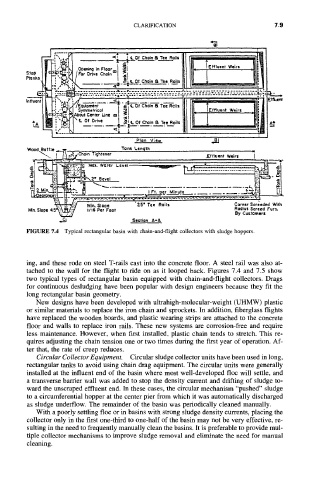
FIGURE 7.4 Typical rectangular basin with chain-and-flight collectors with sludge hoppers.
ing, and these rode on steel T-rails cast into the concrete floor. A steel rail was also at-
tached to the wall for the flight to ride on as it looped back. Figures 7.4 and 7.5 show
two typical types of rectangular basin equipped with chain-and-flight collectors. Drags
for continuous desludging have been popular with design engineers because they fit the
long rectangular basin geometry.
New designs have been developed with ultrahigh-molecular-weight (UHMW) plastic
or similar materials to replace the iron chain and sprockets. In addition, fiberglass flights
have replaced the wooden boards, and plastic wearing strips are attached to the concrete
floor and walls to replace iron rails. These new systems are corrosion-free and require
less maintenance. However, when first installed, plastic chain tends to stretch. This re-
quires adjusting the chain tension one or two times during the first year of operation. Af-
ter that, the rate of creep reduces.
Circular Collector Equipment. Circular sludge collector units have been used in long,
rectangular tanks to avoid using chain drag equipment. The circular units were generally
installed at the influent end of the basin where most well-developed floc will settle, and
a transverse barrier wall was added to stop the density current and drifting of sludge to-
ward the unscraped effluent end. In these cases, the circular mechanism "pushed" sludge
to a circumferential hopper at the center pier from which it was automatically discharged
as sludge underflow. The remainder of the basin was periodically cleaned manually.
With a poorly settling floc or in basins with strong sludge density currents, placing the
collector only in the first one-third to one-half of the basin may not be very effective, re-
suiting in the need to frequently manually clean the basins. It is preferable to provide mul-
tiple collector mechanisms to improve sludge removal and eliminate the need for manual
cleaning.