
Page 142 -
P. 142
CLARIFICATION 7.7
I
W
I
!J
- 1"
i
~i'.~------#so~2 " r~a
H F
¢. 9"® PORT HOLES
(TYp)_ ,,-3"
,,L ~j ~ -r , w.'- ~- .,.
_! _ 4'-6" , 2'-J"
]
I I
Q
0
q
i i
I
2"-9" • I 4'-6"
0
0
I
I I I
I
Q
0 0
° 0
I
Q -@--C
0 0
0
.I
....... 2t ..................................................
.
2
~i ..~..II.IISYN FIBER REINF
LEAN CONC FILL
O EL. 803.50
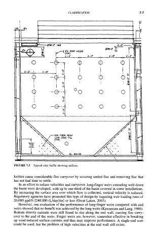
FIGURE 7.3 Typical inlet baffle showing orifices.
locities cause considerable floc carryover by scouring settled floc and removing floc that
has not had time to settle.
In an effort to reduce velocities and carryover, long-finger weirs extending well down
the basin were developed, with up to one-third of the basin covered in some installations.
By increasing the surface area over which flow is collected, vertical velocity is reduced.
Regulatory agencies have promoted this type of design by requiring weir loading rates of
20,000 gpd/ft [248,000 (L/day)/m] or less (Great Lakes, 2003).
However, one evaluation of the performance of long-finger weirs compared with end
weirs showed that no benefit was achieved by the long weirs (Kawamura and Lang, 1986).
Bottom density currents were still found to rise along the end wall, causing floc carry-
over to the end of the weirs. Finger weirs are, however, somewhat effective in breaking
up wind-induced surface currents and thus may improve performance. A single end weir
could be used, but the problem of high velocities at the end wall still exists.