
Page 147 -
P. 147
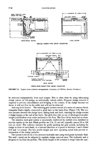
7.12                       CHAPTER SEVEN

           DRIVE SPROCKET WITH


                                                           CROSS  SECTION
                   LONGITUDINAL  SECTION
                                HELICAL-SCREW-TYPE  CROSS COLLECTOR


                        PIVOl


                                     CROSS  SECTION
                           CHAIN-AND-FLIGHT-TYPE  CROSS COLLECTOR
         FIGURE  7.6  Typical cross-collector arrangements. (Courtesy of USFilter, Envirex Products.)


         be  removed independently from  each  hopper.  This  is  often done by using telescoping
         sludge valves,  air lift pumps, or individually valved outlets.  Frequent sludge removal is
         required to prevent consolidation and bridging in the  comers.  If the  sludge become  too
         dense,  it will not flow to the outlet and will not be removed.
           Indexing Grid System.  The indexing grid system consists of a series of concave-faced,
         triangular blades rigidly connected to glide bars on the basin floor (Figure 7.8). The sys-
         tem operates  beneath the sludge layer,  sliding back and forth,  indexing the sludge toward
         a sludge hopper  at the end of the basin. The glide bars ride on top of ultrahigh-molecular-
         weight polyethylene wear strips anchored to the floor. The floor of the basin has no slope.
           The stainless steel  grid system is structurally  reinforced by welded cross members  to
         provide rigidity to the unit. Blade profiles are 2 in. (5 cm) tall, typically spaced 26 in. (66
         cm) on center.  The collector operates  by gently pushing the grid  system,  including the
         sludge in front of each blade,  in a forward  direction at a speed of between 2 and 4 ft/min
         (0.6  and  1.2 m/min). The low profile height and slow operating speed  help prevent re-
         suspension of the sludge particles.
           The system is driven by a low-pressure hydraulic unit using food-grade hydraulic fluid.
         The unit's speed  can be adjusted to regulate sludge  removal rates.  The hydraulic unit is
         designed to oscillate the profiles. The stroke length of the actuator  is longer than the spac-