
Page 284 -
P. 284
OXIDATION AND DISINFECTION 10.29
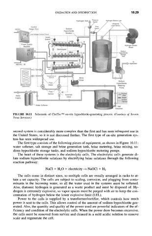
FIGURE 10.11 Schematic of ClorTec TM on-site hypochlorite-generating process. (Courtesy of Severn
Trent Services.)
second system is considerably more complex than the first and has seen infrequent use in
the United States, so it is not discussed further. The first type of on-site generation sys-
tem has seen widespread use.
The first type consists of the following pieces of equipment, as shown in Figure 10.11:
water softener, salt storage and brine generation tank, brine metering, brine mixing, so-
dium hypochlorite storage tanks, and sodium hypochlorite metering pumps.
The heart of these systems is the electrolytic cells. The electrolytic cells generate di-
lute sodium hypochlorite solutions by electrifying brine solutions through the following
reaction pathway:
NaC1 + H20 + electricity -+ NaOC1 + H2
The cells come in distinct sizes, so multiple cells are usually arranged in racks to at-
tain a set capacity. The cells are subject to scaling, corrosion, and plugging from conta-
minants in the incoming water, so all the water used in the systems must be softened.
Also, diatomic hydrogen is generated as a waste product and must be disposed of. Hy-
drogen is extremely explosive, so vapor spaces must be purged with air to keep the con-
centration of hydrogen below the lower explosive limit (LEL).
Power to the cells is supplied by a transformer/rectifier, which controls how much
power is sent to the cells. This allows control of the amount of sodium hypochlorite gen-
erated. Also, the quantity and quality of the power used are powerful indicators of the ef-
ficiency and condition of the electrolytic cells. When the power draw becomes excessive,
the cells must be removed from service and cleaned in a mild acidic solution to remove
scale and regenerate the cell.