Page 289 -
P. 289

Next Page

                              OXIDATION AND DISINFECTION              10.33

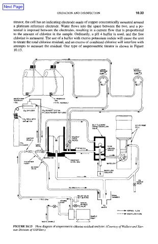
        titrator, the cell has an indicating  electrode made  of copper concentrically mounted  around
        a  platinum  reference  electrode.  Water  flows  into  the  space  between  the  two,  and  a  po-
        tential  is  imposed  between  the  electrodes,  resulting  in  a  current flow  that is  proportional
        to  the  amount  of  chlorine  in  the  sample.  Ordinarily,  a  pH  4  buffer  is  used,  and  the  free
        chlorine  is measured.  The  use of a buffer  with excess  potassium  iodide  will  cause  the unit
        to titrate the total chlorine residual,  and an excess  of combined  chlorine  will interfere  with
        attempts  to  measure  the  residual.  One  type  of  amperometric  titrator  is  shown  in  Figure
        10.13.


                  I
                                                                     LIQUIO
                                                    LIOUIO
                                                    REAG  NT         REAGENT
                                                                     puMp~'* 2


        BUFFER/ACID
                             I GAL
                            (TOTAL RESIOUAL )
                                                    J
             Go~ ........   II II co2 ....  E.~  .....   fKF~


                                                $EL'CLE ....   I   I   3 .....  '~
                                                O~!E!CS~SACKFLUS"    CELL


                                                  [  i   BACKFLU$H
                                                  ~   SOLENOID
                                            1=.
                                                                      SAMPLE
                                                                    ,   VALVE
                          k         TO ORA,~

                                                          CHAMBER
                 q   IT

                                                                IlL  NORMAL FLOW
                                                            ------ID-  BACKFLUSH FLOW


        FIGURE 10.13  Flow diagram of amperometric chlorine residual analyzer. (Courtesy of Wallace  and Tier-
        nan Division of USFilter.)
   284   285   286   287   288   289   290   291   292   293   294