
Page 360 -
P. 360
ION EXCHANGE APPLICATIONS IN WATER TREATMENT 12.19
During the service cycle, all the anions are converted to chlorides at the entrance to
the resin bed. At the exit end of the bed, the chlorides displace some of the remaining ni-
trates left over from the previous cycle, and a small but significant amount of nitrate leak-
age occurs as the service cycle begins. How much nitrate leakage occurs depends on the
total ionic concentration and degree of regeneration. To ensure nitrate levels below 10
ppm as nitrogen, about 10 lb/ft 3 of NaC1 or higher is often considered as a minimum dose
for cocurrently regenerated columns.
Waste Discharge. Regenerant discharge is often a problem in rural areas because of the
potential of nitrates reentering the groundwater.
Nitrate Dumping. The standard type I and type II resins are more selective for sulfates
at the low ionic concentrations of the service cycle. This means that sulfates will domi-
nate the resin bed, occupying the first layer of resin nearest the inlet distributor. Nitrates
will occupy the resin layer directly after sulfates and will be displaced down the column
by sulfates throughout the service cycle. Nitrates will likewise push the chlorides, which
in turn will do the same to bicarbonates. This system is similar to a dealkalizer except
that it is run past the alkalinity breakthrough, until the nitrate breakthrough. Initially the
pH will drop to 5.0 as the resin bed operates as a dealkalizer. After the bicarbonates have
been displaced from the bed, the pH will rise again, and finally the nitrates will begin to
increase in the effluent. The service cycle is usually terminated when the effluent nitrates
reach 20% to 30% of the influent or 10 ppm as nitrogen. If the resin bed is allowed to
continue to process water, the sulfates will continue to load on the resin by displacing ni-
trates, thus increasing the level of nitrates in the effluent to a level that could become as
high as the sum of sulfate plus nitrates in the raw water. In many waters, sulfate levels
are much higher than nitrate levels, so dumping could result in effluent NO3 levels reach-
ing several times as high as the influent levels.
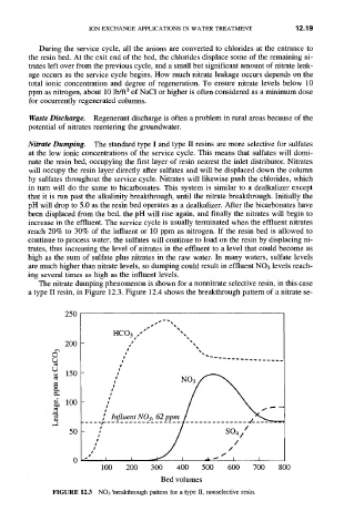
The nitrate dumping phenomenon is shown for a nonnitrate selective resin, in this case
a type II resin, in Figure 12.3. Figure 12.4 shows the breakthrough pattern of a nitrate se-
250
HCO 3 ,-// "",,,
200
C
i I
/
150
e~
~5
100
.... i- go ,_ 62_ / ..............
.3
:' / so4,"
50
/ / J t J I .l, ~" //I / I
100 200 300 400 500 600 700 800
Bed volumes
FIGURE 12.3 NO3 breakthrough pattern for a type II, nonselective resin.