
Page 440 -
P. 440
MEMBRANE PROCESSES 13.37
Pumping Requirement. UF and MF systems typically require several pumps (depend-
ing on the specific system and application): feed or permeate pump, recirculation pump,
backwash pump, cleaning pump, chemical transfer and feed pumps, and vacuum pump
(for vacuum-type systems). In a few systems, the feed or permeate pumps have been elim-
inated by the use of gravity head or siphons.
The feed pump for a system is sized to meet the maximum required pressure and flow
rate considering the membrane type, temperature, flux, piping and other pressure losses
(separate from the transmembrane pressure), and degree of fouling over time. Addition-
ally, some systems are designed for increased feed flow rates during part of the operating
cycles. For example, one major MF manufacturer with a proprietary gas backwash sys-
tem uses an increased-capacity feed pump to provide the desired feedwater flow rate for
flushing out suspended solids removed from membranes by the gas backwash. Typical
feed pressures for pressure-type MF and UF systems used in municipal water treatment
range from 15 to 60 psi (100 to 414 kPa), and from -1 to -12 psi (-6.9 to -83 kPa)
for vacuum-type systems.
If the design includes retentate stream recirculation (common in feed-and-bleed cross-
flow operating mode), recirculation pumps are sized to overcome pressure losses through
the system while providing the desired recirculation flow rates, typically 3 to 6 times
greater than the source water flow rate.
Backwash pumps, if required, are sized for the specific needs of the membrane sys-
tem and commonly provide targeted flow to the filtrate or permeate side of the membranes
at low pressure.
Membrane Module Arrays. MF and UF systems are typically designed using multiple
parallel units. For large-capacity systems, multiple groups (each containing several mem-
brane units) form modular arrays or wains. Each array has common manifold piping to
control service flows, backwashing, and cleaning-in-place (CIP).
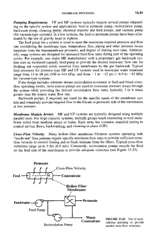
Cross-Flow Velocity. Many hollow-fiber membrane filtration systems operating with
"inside-out" flow patterns require specific minimum flow rates to provide sufficient cross-
flow velocity to control fouling and to flush retentate from the fibers. Typical cross-flow
velocities range up to 3 ft/s (0.9 m/s). Commonly, recirculation pumps recycle the fluid
on the feed side of the membranes to provide adequate velocities (see Figure 13.23).
Permeate
f f f f/Cross-VlowVelocity
Feed ---~) - ~-- -~-- ~ ) ' Concentrate
) ) ) ~"'~ Hollow Fiber
Membranes
Feedwater--~ ~'~ ~Feed Pump ,Permeate~ Waste
FIGURE 13.23 Use of recir-
Concentrate
culation pumping to provide
Recirculation Pump
needed cross-flow velocities.