
Page 459 -
P. 459
ACTIVATED CARBON PROCESSES 14.7
feed is infrequent and the maximum feed rate is less than a few hundred pounds per hour.
The feed system usually includes a bag-loading hopper, an extension hopper, a dust col-
lector, a dissolving tank or vortex mixer tank, and an eductor.
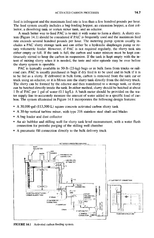
A much better way to feed PAC is to mix it with water to form a slurry. A slurry sys-
tem (Figure 14.1) should be considered if PAC is frequently used and the maximum feed
rate exceeds several hundred pounds per hour. The metering pump system usually in-
cludes a PAC slurry storage tank and can either be a hydraulic diaphragm pump or ro-
tary volumetric feeder. However, if PAC is not required regularly, the slurry tank sits
either empty or full. If the tank is full, the carbon and water mixture must be kept con-
tinuously stirred to keep the carbon in suspension. If the tank is kept empty with the in-
tent of mixing slurry when it is needed, the taste and odor episode may be over before
the slurry system is operable.
PAC is typically available in 50-1b (23-kg) bags or in bulk form from trucks or rail-
road cars. PAC is usually purchased in bags if dry feed is to be used and in bulk if it is
to be fed as a slurry. If delivered in bulk form, carbon is removed from the tank car or
truck using an eductor, or it is blown into the slurry tank directly from the delivery truck.
The slurry can be formed by the eductor and then transferred to a storage tank, or slurry
can be batched directly inside the tank. In either method, slurry should be batched at about
1 lb of PAC per 1 gal of water (0.1 kg/L). A batch meter should be provided on the wa-
ter supply line to accurately measure the amount of water added to a specific load of car-
bon. The system illustrated in Figure 14.1 incorporates the following design features:
• A 30,000-gal (113,500-L) square concrete activated carbon slurry tank
• A 30-hp vertical turbine mixer, with type 316 stainless steel shaft and blades
• A bag loader and dust collector
• An air bubbler and stilling well for slurry tank level measurement, with a water flush
connection for periodic purging of the stilling well chamber
• A pneumatic flu connection directly to the bulk delivery truck
ACTIVATED CAREON FEED BUILDING
DUST
COLLECTOR
"~ / ..... I~ L• OAAGCER P ............
CONNECTION
,.
.2"× 1'/="
2" CAP FOR FUT.- ..... -- ~ ~ . I R~D X g'
~// b I
~x
2"OVERFLOW ~ 1.-..-2 I ;' i
l J
DRAIN " ~ 2,, CAP FOR FUT 3
i/~ SAMPLE ~("~ FLASH MiX STRUCTURE )
...L
CONNECTION pG O'1~"
FIGURE 14.1 Activated carbon feeding system.