
Page 494 -
P. 494
15.4 CHAPTER FIFTEEN
" :t~on
2
rlr~
foot-rlng wPe
t-,0¼"- t
(a)
6 safety plugs, 3 each end 1 "" ,
pipe
2t
l- '1
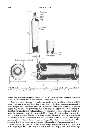
FIGURE 15.1 Dimensions of standard chlorine cylinders. (a) A 150-1b cylinder. (Courtesy of PPG In-
dustries, Inc., Pittsburgh, Pa.) (b) A 1-ton cylinder. (Courtesy of the Chlorine Institute, Inc.)
fusible plug that melts at approximately 158 ° F (70 ° C) and releases some liquid chlorine
to cool the cylinder before a more serious accident can occur.
Chlorine is most often fed by withdrawing gas from the top of the container, and the
reduced pressure above the liquid then causes some of the liquid to evaporate, providing
additional gas. The maximum withdrawal rate with this method is about 40 lb per day (18
kg per day) for a 150-1b cylinder and 400 lb per day (181 kg per day) for a 1-ton cylin-
der. Maximum continuous withdrawal rates for containers of other sizes can be approxi-
mated by comparing the surface area available to absorb the heat required to replace the
heat of evaporation lost. If chlorine is being used in this manner, the containers should
be maintained in an environment that can be heated to 65 ° F (18 ° C). The design-
maximum 24-h withdrawal rate of a system designed to withdraw gas from the top of the
container should not exceed the continuous withdrawal rate of the containers on-line.
Bulk Shipment of Chlorine. Chlorine tank barges have either four or six tanks, each
with a capacity of 85 to 185 tons (77 to 168 t), and must comply with Coast Guard reg-