
Page 51 -
P. 51
4,4 CHAPTER FOUR
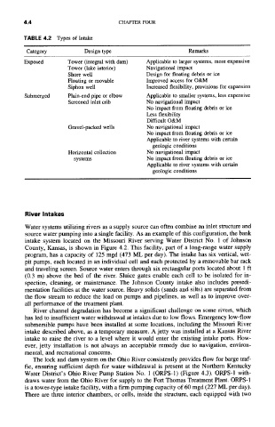
TABLE 4.2 Types of Intake
Category Design type Remarks
Exposed Tower (integral with darn) Applicable to larger systems, more expensive
Tower (lake interior) Navigational impact
Shore well Design for floating debris or ice
Floating or movable Improved access for O&M
Siphon well Increased flexibility, provisions for expansion
Submerged Plain-end pipe or elbow Applicable to smaller systems, less expensive
Screened inlet crib No navigational impact
No impact from floating debris or ice
Less flexibility
Difficult O&M
Gravel-packed wells No navigational impact
No impact from floating debris or ice
Applicable to river systems with certain
geologic conditions
Horizontal collection No navigational impact
systems No impact from floating debris or ice
Applicable to river systems with certain
geologic conditions
River Intakes
Water systems utilizing rivers as a supply source can often combine an inlet structure and
source water pumping into a single facility. As an example of this configuration, the bank
intake system located on the Missouri River serving Water District No. 1 of Johnson
County, Kansas, is shown in Figure 4.2. This facility, part of a long-range water supply
program, has a capacity of 125 mgd (473 ML per day). The intake has six vertical, wet-
pit pumps, each located in an individual cell and each protected by a removable bar rack
and traveling screen. Source water enters through six rectangular ports located about 1 ft
(0.3 m) above the bed of the river. Sluice gates enable each cell to be isolated for in-
spection, cleaning, or maintenance. The Johnson County intake also includes presedi-
mentation facilities at the water source. Heavy solids (sands and silts) are separated from
the flow stream to reduce the load on pumps and pipelines, as well as to improve over-
all performance of the treatment plant.
River channel degradation has become a significant challenge on some rivers, which
has led to insufficient water withdrawal at intakes due to low flows. Emergency low-flow
submersible pumps have been installed at some locations, including the Missouri River
intake described above, as a temporary measure. A jetty was installed at a Kansas River
intake to raise the river to a level where it would enter the existing intake ports. How-
ever, jetty installation is not always an acceptable remedy due to navigation, environ-
mental, and recreational concerns.
The lock and dam system on the Ohio River consistently provides flow for barge traf-
fic, ensuring sufficient depth for water withdrawal is present at the Northern Kentucky
Water District's Ohio River Pump Station No. 1 (ORPS-1) (Figure 4.3). ORPS-1 with-
draws water from the Ohio River for supply to the Fort Thomas Treatment Plant. ORPS-1
is a tower-type intake facility, with a firm pumping capacity of 60 mgd (227 ML per day).
There are three interior chambers, or cells, inside the structure, each equipped with two